Building a state machine
In my last significant Arduino project, I came across the concept of a state machine. I didn’t have time to look into it then, but when I started to think about the software for this slider, it came to mind again, and I decided to investigate.
What is a state machine?
Paraphrasing from Wikipedia:
A system that can be in exactly one of a finite number of states at any given time. The state machine can change from one state to another in response to some external inputs; the change from one state to another is called a transition. A state machine is defined by a list of its states, and the conditions for each transition.
When we’re thinking about useful machines – things that do something, this minimal definition could be expanded a little. Specifically, in each state, there is some sort of output: a light flashes, a motor turns, or an error message is logged. Here’s a description with more of a hardware focus, from State Machines and Arduino Implementation:
States
An embedded system should at any given time be in a defined state, whether it is “moving left”, “door open”, “stopped”, “init”, “error” or any other imaginable state. The states and the transitions between them make up the main structure of the state machine.Inputs
Inputs are what makes the system switch states and can for instance be switches, buttons and sensors or any other typical embedded input.Outputs
Outputs in a state machine can be motor movement, lights or any other typical embedded output.
Why is it useful?
I was initially drawn to state machines because it seemed like a natural model for my slider: it’s always going to be in one of a number of states: calibrating itself, waiting start a traverse, doing the actual traverse, stopping in case of an error, etc.
However, I quickly realised there are a couple of related benefits.
Simplifies event handling
From UML state machine - Wikipedia:
The concept of a FSM is important in event-driven programming because it makes the event handling explicitly dependent on both the event-type and on the state of the system. When used correctly, a state machine can drastically cut down the number of execution paths through the code, simplify the conditions tested at each branching point, and simplify the switching between different modes of execution. Conversely, using event-driven programming without an underlying FSM model can lead programmers to produce error prone, difficult to extend and excessively complex application code.
For me, this is huge. I have to consider so many possible inputs, especially when looking at all the ways the slider might go wrong. So if I can isolate its behaviour into a set of discrete states, I can simplify the inputs I need to worry about. e.g. I don’t need to worry about changes to the speed control whilst calibrating; I don’t need to poll the end-stop switches while the slider is stationary.
Forces you to solve most problems before writing any code
You can’t build a state machine without a clear model of the states, inputs, transitions, and outputs. This model is usually drawn as a state machine diagram. As soon as you get into writing code, and testing it with hardware, many tings can go wrong, and it’s difficult to see sometimes whether the problem is in the system you’re making, the logic of the code, or you’ve just left a semi-colon off the end of a line, or forgotten to connect a button to ground.
As I was drawing my state machine diagram, I found that I had to think about all of the error handling, the user interface, and flow of actions before writing any code. And I solved almost all the hard problems in the course of drawing the diagram. I think if I’d dived straight into code, I would have been in a tangled mess very soon.
Drawing a state machine diagram
I used the excellent Omnigraffle software to draw my diagrams. Note that these are not flow charts. There are several resources (see below) that go into lots of detail about how to draw a syntactically correct diagram, even some dedicated modelling software, but I was mostly concerned with getting the basics right, capturing:
- All possible states
- All relevant events that could happen in each state and what transitions these would trigger to other states
Here was my first rough attempt:
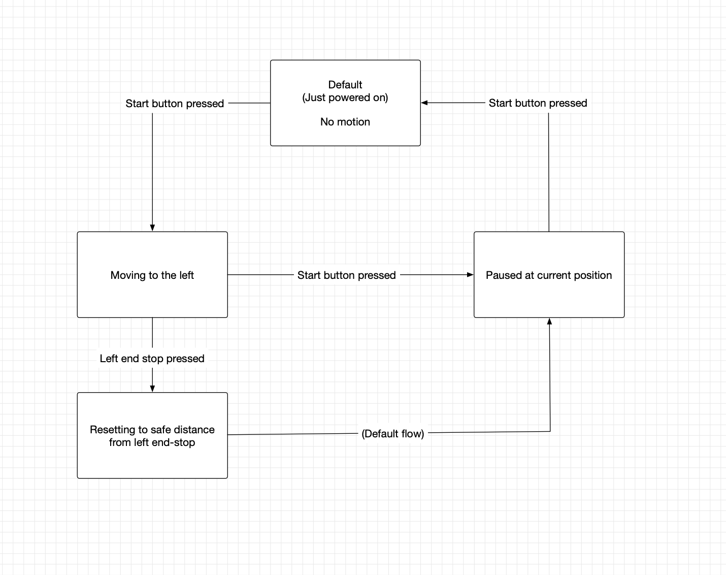
After several hours work, I ended up with something more comprehensive, and with an alarming number of arrows.
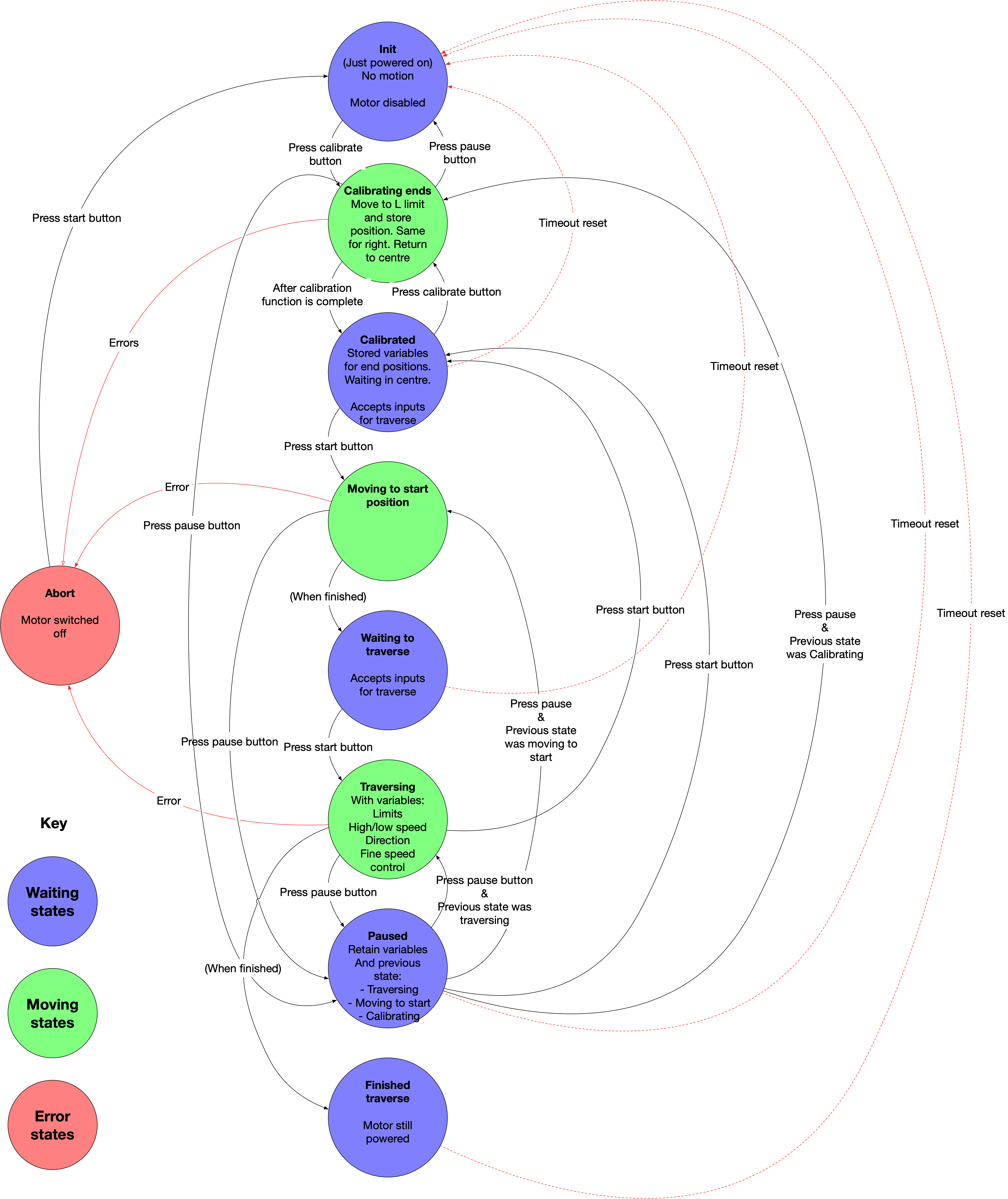
In this diagram, each circle is a state, and each arrow is a transition. The flow is pretty linear, going from top to bottom one state after the next, and the only deviation from the path coming if there is an error (typically the slider hitting an end-stop when we’re not expecting it), or the user pauses or cancels an operation.
So while it might look complex, in fact it captures all the functionality I need to build (mostly things that are done in the green circles: such as calibrating the ends of the slider) and the inputs I need to listen for – and critically when I do and don’t need to listen for them. This made coding even this complex machine way easier.
After building most of this, and then testing with my prototype hardware, I realised a major flaw in my design. In this model, a key step is calibration. After starting up, the slider moves to each end of the rail, until it hits each end-stop, to get the position data for each end. It then uses this to move to one end (depending on the direction the user sets), and also to perform the actual traverse to the other end (so it knows how fast to go for a given duration, and also when to stop).
Once it’s calibrated, the motor must remain powered to keep the spindle locked in the same position. If the user were to move the gantry by hand after calibration, all of that data would become incorrect. That draws power, and also creates noise, so I wanted to include transitions so it could timeout back to a startup position after a while, or the user could reset it by hand.
Simplifying
The calibration process (and these extra events) added complexity and time to the process, and I soon got bored of going through all these steps when testing my code. So I wondered if I could simplify things. What would happen if I just ditched the calibration process, and worked on the assumption that the slider never knew where it was, or (until it hit a stop switch) where the ends were?
Sure enough, as I removed this state from the machine, other states also became redundant, and my next version was drastically simpler:
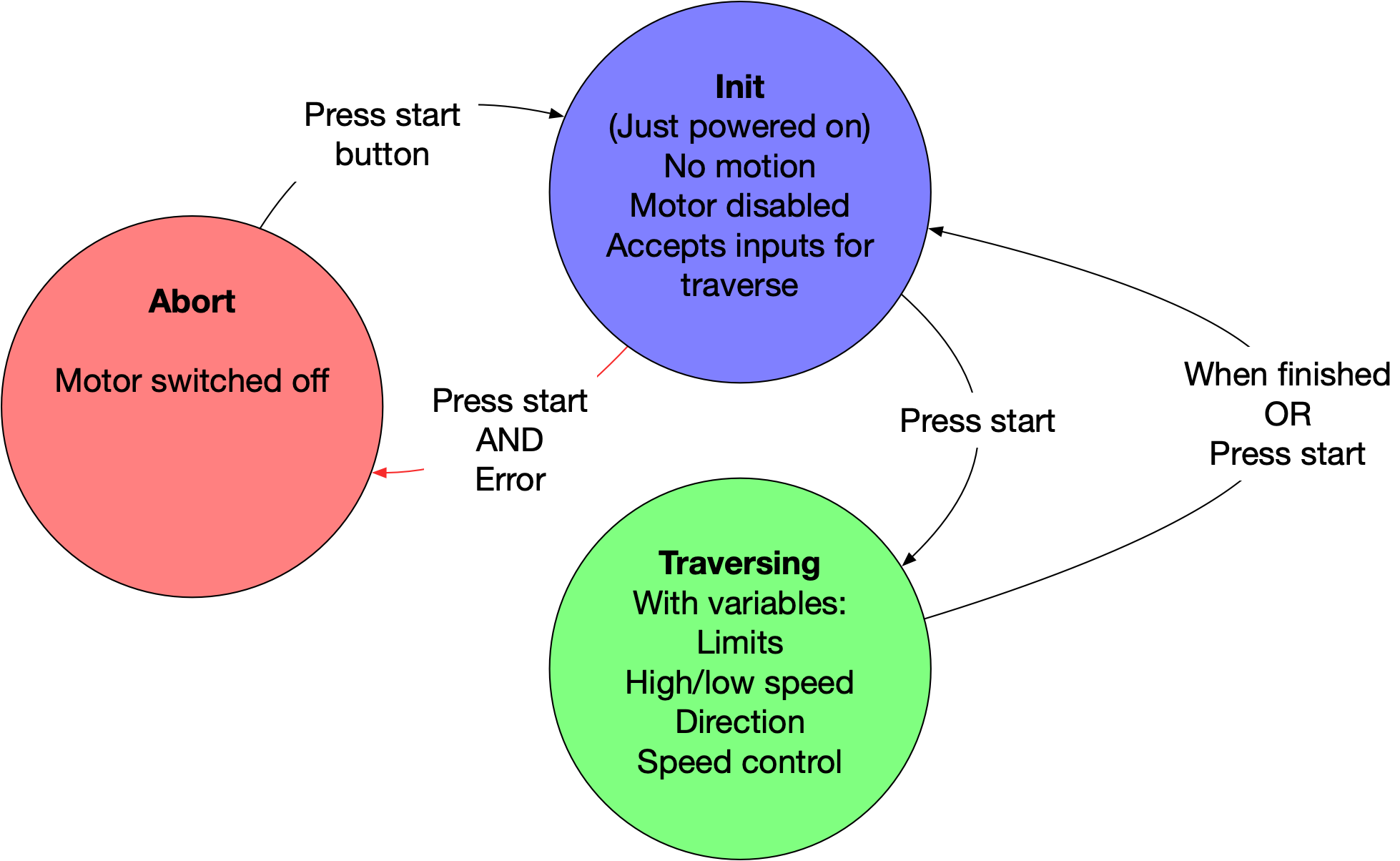
With no calibration step, the slider is ready to accept input as soon as it’s switched on. Rather than moving from one end all the way to the other, in the direction the user specifies, it just moves in that direction from wherever it happens to be at that point, and stops when it hits an end stop. No data about current location or the position of end-stops needs to be retained, so the motor can be switched off whenever it’s stationary. There’s no need for timeouts, manual resets or soft pausing (remembering this data for when the pause is released).
I’d written all the code for the complex version by the time I figured this out. However, it was a useful lesson in complexity: as you add states to a state machine, complexity increases non-linearly; and can quickly get out of hand. I was also able to dig deeper into the stepper library I’m using. And it was kind of cool watching the machine calibrate itself; so I’m kind of sad to see that go.
I’ve posted the old – complex – code in the repo in case anyone’s interested: fab-slider/arduino-code/old-complex-state-machine at master · andrewsleigh/fab-slider · GitHub
Scaffolding in code
The code to handle this in Arduino is very simple. First, set up an enum to hold all your possible states:
enum possibleStates {
  INIT,
  TRAVERSING,
  ABORT
};
Then create a variable of this type to track the current state:
enum possibleStates currentState;
Then in your main loop() function, use a switch statement to control flow through the states:
switch (currentState) {
  case INIT:
    // do stuff you need to do on startup
    // e.g. switch the motor off, get inputs for direction, speed, etc.

    break;

  case TRAVERSING:
    // move the slider with whatever parameters the user set
    // don't get any more inputs from user controls
    // stop and pull back when you hit an end stop

    break;

  case ABORT:
    // stop the motor, print error messages

    break;
}
Further reading
These are some resources I found helpful
On state machine theory
- Modeling Software with Finite State Machines (book)
- A State Machine Crash Course
On diagrams
- State diagram - Wikipedia
- UML state machine - Wikipedia
- StarUML documentation: Statechart Diagram
- UML State Machine Diagrams - Overview of Graphical Notation
On state machines in Arduino
Next steps
Some other things I want to talk about soon: