Gantry
The gantry is basically just a flat plate with mounting holes for attaching different devices, and for the wheels and timing belt.
Ooznest sell an aluminium gantry platefor the 8040 V-slot C-beam (in a kit form with delrin wheels for £25). This C-beam has a 40 mm channel down the middle, so it should be adaptable for two lengths of 2020 mounted 40 mm apart.
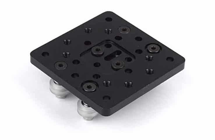
They also have a simpler plate designed to straddle a single 2020 rail. (£24 in a kit with 4 wheels).
These are really nice plates, and you could certainly make something similar out of laser-cut acrylic.
Mounting a camera
Camera mounts are standardised around a 1/4” screw. Even mounts for phones typically have a 1/4” threaded hole so thy can be mounted on standard camera accessories, like tripods. So this is a good fitting onto which I could fit any number of off-the-shelf mounting parts, such as this camera mount.
An aluminium baseplate could have a threaded hole to accept a 1/4” bolt. I can’t create a threaded hole in an acrylic baseplate but I could create a two-layer plate, where the top layer has a hexagonal hole to capture a nut into which a bolt could be threaded.
Note: the camera needs to be able to site flush against the top face of the gantry. So any other fixings – for example the timing belt, or the bolts for the wheels – need to be recessed or otherwise out of the way. With a metal (or wooden) plate, this is easy enough, you could use countersink-headed bolts. But you can’t laser-cut acrylic with countersink holes, so again, I’m leaning towards a 2-layer design. 3D printing would be another option.
Attaching the timing belt
The Adafruit slider uses a vertical drive shaft, meaning that the timing belt is also vertical. They use a nice kinked channel in the gantry plate to hold the (continuous loop of belt) belt in place.
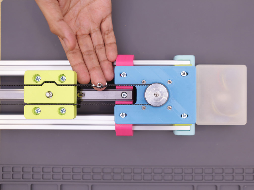
This picture also shows the use of a belt tightener.
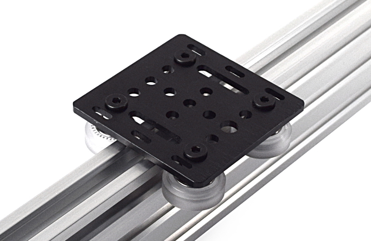
The Ooznest design uses a drive shaft in a horizontal orientation, so the belt is transposed through 90°. You can see the slots on the edges of the gantry plate through which you could thread each end of the timing belt, to be secured with a cable grip.
This approach allows you to cut the belt to whatever size works. I think this is a better approach for me, assuming I use a laser-cut gantry.
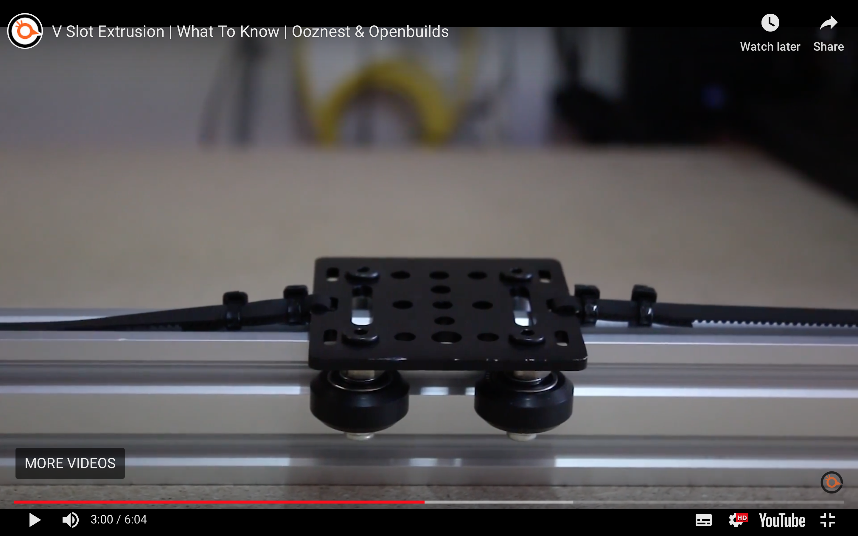
Mounting bearings
This image of the Ooznest gantry show the kind of method I’d like to use. As they use an aluminium plate, they’re able to cut recessed holes for the bolt heads to allow them to sit flush with the top surface. I think I could achieve the same effect with a 2-layer laser-cut acrylic plate. Or by conventional manual countersinking in a MDF laser-cut plate.
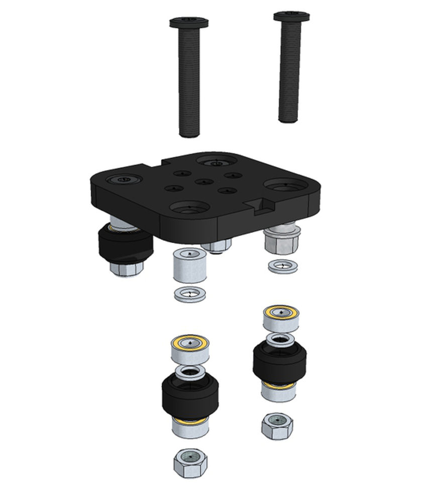
Some kits (e..g the Ooznest kit) use eccentric spacers to allow the wheels to be adjusted in fine increments. A simpler – and perhaps adequate – solution would be to use slots rather than round holes to accept the wheel bolts.
Wheels/bearings
I’m looking to mount 4 wheels on bearings in a horizontal orientation underneath my gantry. It’s possible I can 3D-print the wheels themselves, but I’d still need the bearing, bolt and spacer assembly. So I’m inclined, for version one, to buy the complete assembly, and see if I can swap out some commercial parts for DIY versions later. Apart from anything, I’d like to see what difference it makes to the motion of the gantry. But wheel kits are expensive:
- Ooznest Delrin Dual V Wheel, including M5 bolt and 6mm spacer: £4.44 each
- Ooznest Mini V Wheel Wheel, including M5 bolt and 6mm spacer: £3.44 each
Alternatively, cheaper versions are available on Amazon, etc. For example, BIQU Equipment Wheel with Bearings (Pack of 5) (£6) or Samje Wheels (Pack of 5) (£9)
Belt
GT2 Belt seems to be pretty standard. That means it has a pitch of 2 mm between the teeth. The 6 mm wide belt seems to be the most common.
Pulleys and/or bearings
I’ll need at least one pulley (a toothed wheel), that can be mounted to the motor drive shaft. At the other end of the rail, I can use a bearing to allow the belt to move freely.
The image below shows the belt mechanism at one end of the Adafruit slider. Note how a smooth bearing is used, not a toothed pulley:
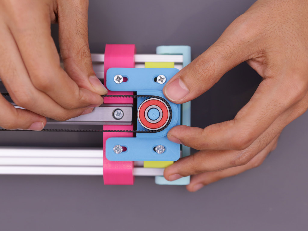
Pulleys are specified by a given number of teeth, for a certain pitch of belt. e.g. a 30 tooth GT2 pulley. I need a 5 mm bore for the motor drive shaft, with fixing via a grub screw, and a width of 6 mm or more for the 6 mm belt.
One factor I might want to consider here is the diameter of the pulley. According to Ooznest, a 30 tooth GT3 pulley (note: the description here says GT3, not GT2, but I think that may be a typo) will allow the belt to loop around both sides of a 20 mm extrusion.
I plan to run the timing belt in the cavity between two rails of aluminium extrusion, so this may not be an issue. However, if I want to include an angled rod between the two rails to pivot the gantry along its traverse, I might want to use a bigger pulley to leave some space here. The pulley and the opposite-end bearing should have roughly the same diameter.
Fortunately, it is possible to calculate the diameter of a pulley if you know the number of teeth and the pitch.
Diameter
= Number of teeth * Pitch / Pi
= 30 * 2 mm / 3.14
= 19.1 mm
For a 20 tooth pulley, this works out at 12.7 mm. Obviously this gives you the diameter on the inside of the belt, so to check for clearances, you need to allow for the thickness of the belt, and also the diameter of any fences on the pulley.
It’s possible to laser-cut pulleys, and I think this would be an experiment worth doing, to compare with commercially made pulleys.
Pulleys:
- Adafruit Aluminum GT2 Timing Pulley - 6mm Belt - 36 Tooth - 5mm Bore: $12
- Ooznest GT2 Pulley 20 Tooth: £2.90
- Ooznest GT2 (I think) Pulley 30 Tooth: £8.75
Bearings:
- Ooznest only sell 5 mm wide bearings. If I’m using a 6 mm belt, these won’t be big enough
- Amazon 10 x 26 x 8 mm bearings, pack of 3 (£3.50)
- RS have many 6-7 mm wide bearings at 19 mm diameter (around £2 each)
You can also get ‘idler pulleys’, essentially a pulley mounted on a bearing, which might be a better choice for the end opposite the motor.
- Amazon: 20 teeth 5mm Bore 6mm width (Pack of 5) (£7)
Or you can buy complete kits of belts, pulleys and idler pulleys (This, £15 on Amazon, or this, just the belt and 2 pulleys for £9)