Electronics housing
I probably spent more time on this aspect of the build than any other part. As I changed the shield design, I prototyped different cases, but could never get them down to a reasonable size.
Mounting to the main structure of the slider
I want the whole thing to be one object, but there are very few possible mounting options for the electronics. I originally thought I could mount it to the side, but after making several prototypes based on this assumption, I realised that it would interfere with the gantry. An obvious mistake in retrospect.
After I switched to a single 2-sided board design, I was able to get the size of the electronics down enough that end-mounting was possible.
Making assembly possible
The biggest problem with the housing is putting it all together. The housing itself has to be mounted to the frame. The board has to be put into, and then fixed to, the housing. The controls, if separate, need to be fixed to the housing, and then connected to the board. And then a lid or screen needs to be fixed to close everything off.
Satisfying all these requirements at the same time was very difficult, and forced me to simplify my board design, in particular so that the controls are fixed to the board, not the panel.
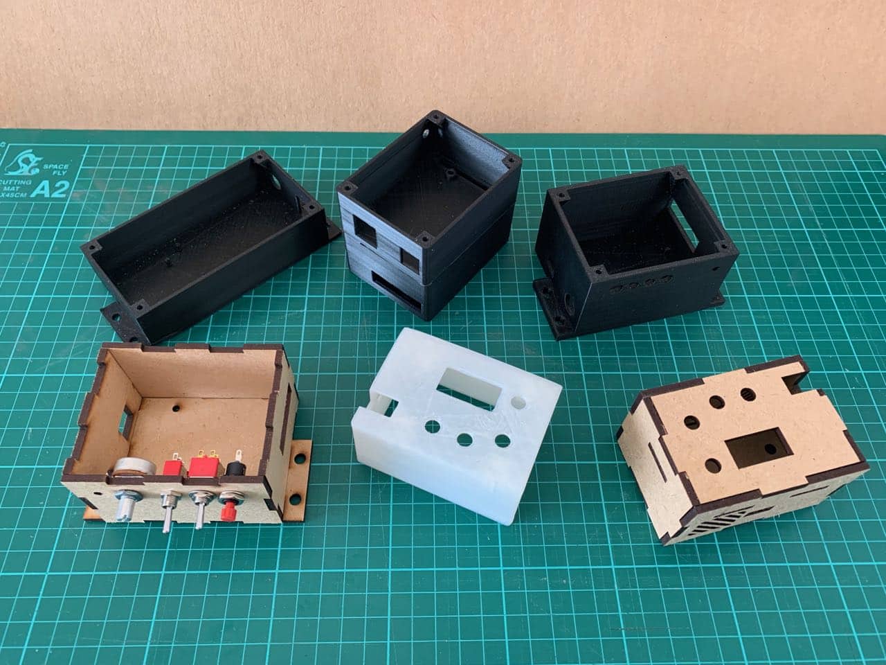
Mounting posts and plates
I tried various 3D-printed cases with short pillars with 3 mm holes onto which the board could be screwed with M3 machine screws. I couldn’t bolt screws through from the outside of the case, because I wanted it to be flush, and with a 2-3 mm case thickness, there wasn’t enough room to add a rebate for the screw head.
However, I wasn’t able to print with good enough fidelity and tolerances to make that work with M3 machine screws. In retrospect, using self-tapping screws would have likely worked. This is often how boards are mounted onto plastic cases in commercial products.
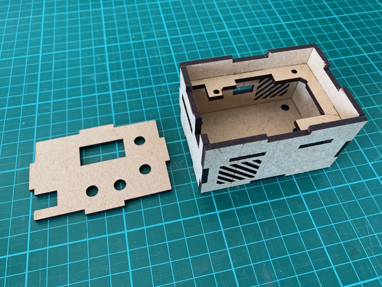
I also tried a version (prototype pictured below) with a mounting plate inside the enclosure but it was very difficult to get this compact enough to be viable, while still allowing room for all the parts to be put into the case.
Ventilation
The TMC2130 driver has a pretty large heatsink (relative to the A4988 drivers) and the documentation recommends fan-assisted cooling. I suspect this may be more of an issue if you’re using it to drive a 3D printer, but still, I wanted to include some passive ventilation at least.
Connections outside the casing
While the electronics are as integrated as possible, some connections do need to be made to other parts of the machine, specifically, to the end-stop switches and the motor. I included 2 right-angle male headers on the board to enable this, and positioned them so an opening could be made in the case for connection.
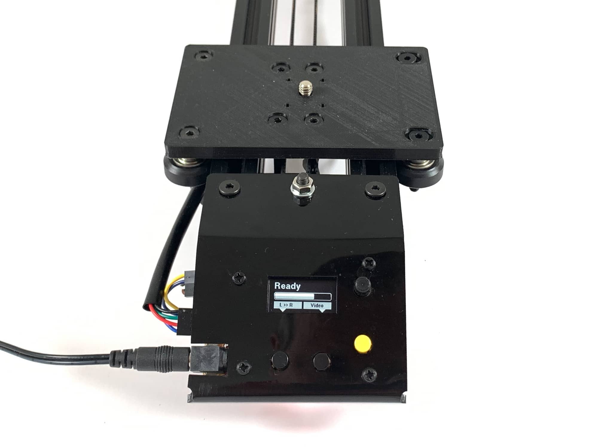
Switching to a faceplate housing
Inspired by the design of the Creality Ender 3, I decided to try mounting the electronis to a faceplate, and leaving them unenclosed on the other sides.
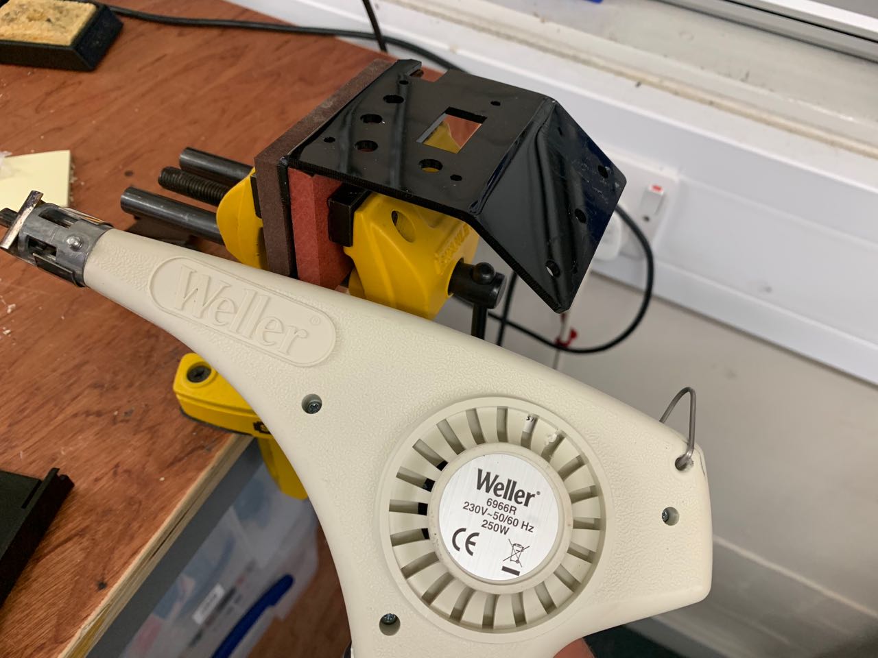
I cut a plate from 3 mm black acrylic, and bent it to shape with the help of some pieces of MDF, a vice and a heat gun. While a simple couple of folds, I was pleased with how easy it was to control this and get a good result, even with these primitive tools.
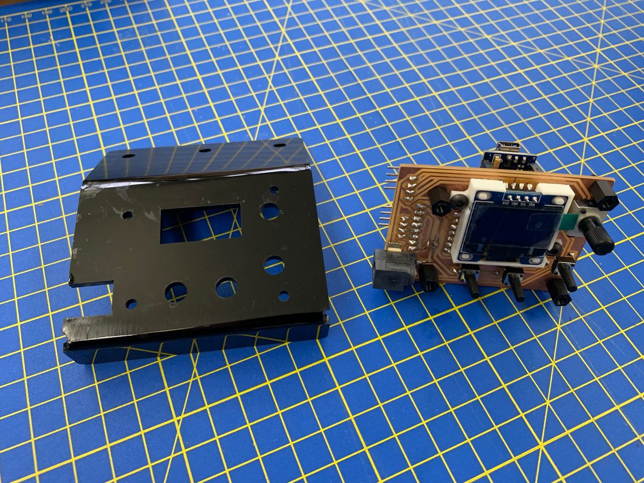
This has two mounting holes on top so it can be fitted to the rails, and one central hole on top to take the idler pulley, which was previously attached to a separate plate here.
I’m very happy with this design, which is a lot more elegant than my previous attempts, and offers plenty of ventilation(!), perhaps at the expense of a little protection.
The faceplate design and OLED display mount are in the Git repo: fab-slider/3d-parts/v1/electronics-face-plate