Building the mechanism
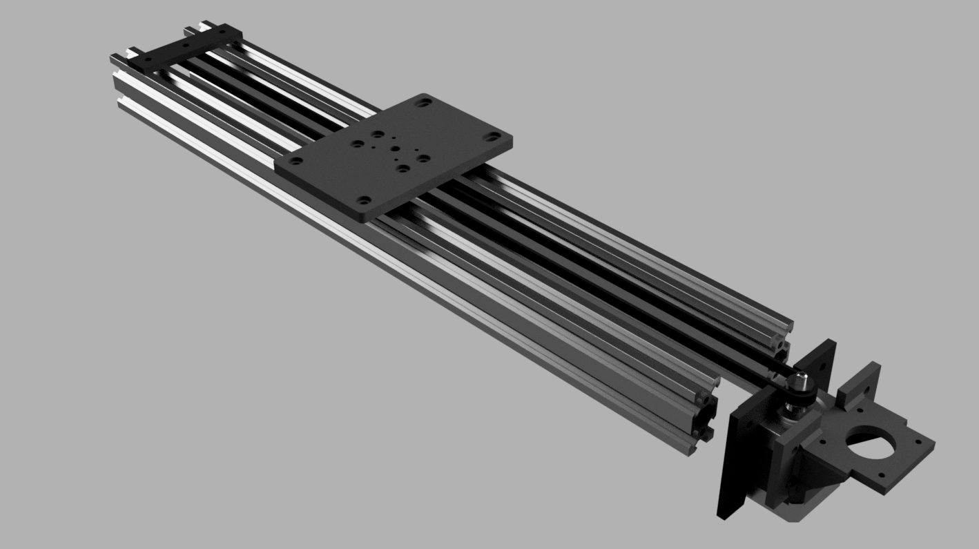
I had a few days access to the fablab, so I tried to make as much of the physical hardware as I could so I could work on the motion control software later. One of my original aims for the project was to try and learn more about 3D printing, and I was very successful in this aspect. I modelled the whole assembly in Fusion 360 and 3D-printed several iterations of key parts on our Creality CR-10 printer. I had a lot of fun with it.
All the parts mentioned in this posts are in the GitHub repository. Links are included in each section.
End-caps (GitHub repo)
This design requires caps at each end to hold the rails in position, and to act as feet for the whole assembly. This approach is simpler, and more physically sound than many of the other approaches I’ve seen, which rely on complex 3D-printed parts that fit into the V-slot, or special V-slot right-angle brackets, that introduce more hardware, and with it, cost and instability.
However, here is one drawback, it requires tapped holes in the ends of the extrusion, which don’t come as standard.
Tapping holes in the V-slot
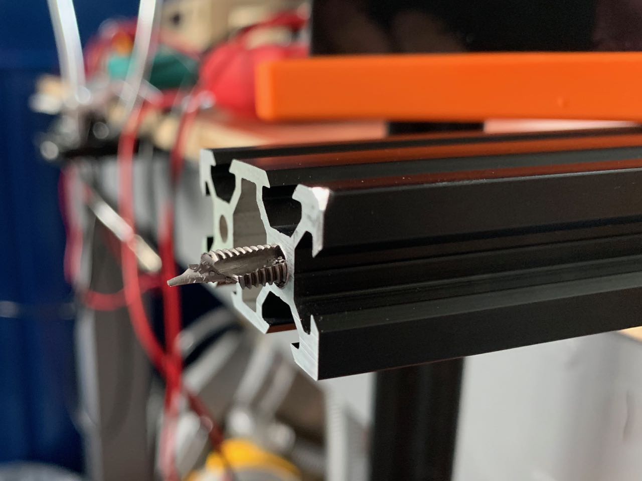
The V-slot extrusion has holes in each end, which can be tapped to an M5 thread. Some suppliers (like Ooznest) will do this for you, or you can do it yourself. I thought I would ask them to tap some of the holes and do the rest myself, since I’d like this to be as DIY as possible.
However, despite having had some experience tapping holes before – and watching some good videos – I had limited success. I shattered one tap, leaving it stuck in the hole, and after a little more practice, on my three remaining holes, only did a good job on two of them.
So I ended up using the pre-tapped holes on the business end of the slider, where the motor is mounted, and on the other end, using a combination of some of my tapped holes, and right-angle v-slot brackets to mount the end-cap.
For a future version, I would like to design a mounting system that doesn’t rely on tapped holes at all, as there is too much room for error.
Gantry (GitHub repo)
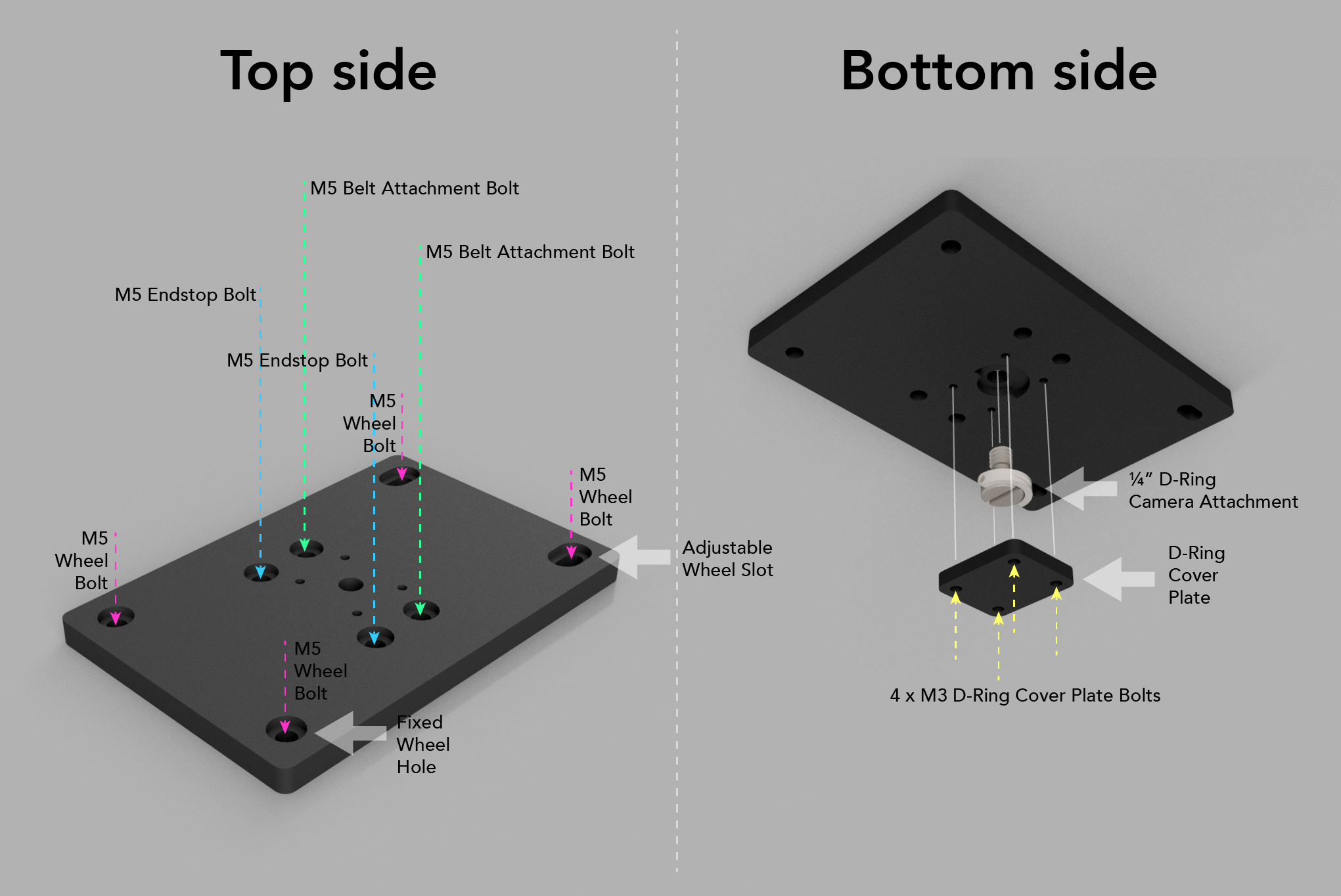
This is a surprisingly complex part! It needs to perform a few functions:
- Hold a camera (by embedding a 1/4” screw)
- Attach to the timing belt
- Make contact with the end-stop switches at each end of the slider
- Mount onto the wheels which slide in the V-slot.
The camera screw needs to be captured inside the gantry in some way, so I added a small screw-in plate, which captures it from the underside.
The belt is attached to the gantry by two bolts that protrude underneath it. Each end of the belt can be wrapped around one of the belts and secured with a cable tie. This seems to work pretty well in practice.
There are two more bolt-mounting holes for bolts that protrude underneath the gentry and should hit the end-stops at each end of the traverse. I suspect I actually only ned one though. This is something that needs to be worked out when I’m working on the end-stop code.
Wheels
I bought some relatively cheep wheels, which are OK, though don’t turn as easily as I expected. However, this is my first experience woking with bearings, so I don’t know what I should expect.
Wheel adjustment
I mounted one pair of wheels through circular holes in the gantry, and the other set through elongated slots, perpendicular to the rails, to allow the wheel spacing to be adjusted slightly.
This worked OK in the 3D printed gantry (less so in the laser-cut acrylic version, where there is less friction between the nut and the gantry). It also made it possible to mount and demount the gantry even when the end-caps are fitted, and it can’t be slid off an end.
Washers
Initially, I used washers on the wheel assembly – it’s just a convention that I’ve got used to, to add washers to enable free rotation of parts against a tightened nut. But of course, in this assembly, the bearing itself is designed to be held firm in the assembly at the centre, but to rotate freely on the outside. And I found the washers were interfering with this, so I removed them.
Motor backet (GitHub repo)
This was a simple part to design. It just needs to hold the motor at 90° against the end of the slider rails.
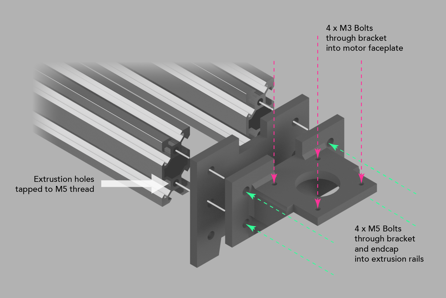
However, my current design is attached to the rails by bolting through the end-cap into the threaded holes in the extrusion. That’s a solid design, but perhaps less easy for others to replicate. So for a future design, it would be good to think about an alternative approach that doesn’t relay on these threaded holes.
End-stops (GitHub repo)
I already had some end-stop switches left over from a previous project. I just had to find a way to mount them. They do have tiny holes, that perhaps might take an M2 bolt, but I didn’t have any of those, so instead, found a nice clip on Thingiverse.
End-stop wiring
My switch wiring is currently way more complex than it likely needs to be, but I thought it was worth wiring the switches for maximum flexibility at this stage, even if I make things simpler later one.
The switches have 3 contacts, labelled:
- NO – Normally Open
- NC – Normally Closed
- C – COM/Common
An end-stop should be activated when it is pressed, but ideally, it should also prevent motion of the gantry if there is a defect with the switch, for example, one of the wires is cut, or the contact is dirty. So its default behaviour (no continuous circuit between NO and C) should be ‘stop movement’. This should also be the behaviour when the switch is pressed (continuous circuit between NC and C; no continuous circuit between NO and C). And when the switch is open (continuous circuit between NO and C), and the switch is receiving current, the behaviour should be ‘allow movement’.
This page explains it well:
You want a normally closed (NC) switch. Meaning you need a switch which connects two poles when not triggered. … When the switch is off, it connects signal to ground. When the switch is triggered, the ground connection is cut and the signal is connected to 5v through the pull up resistor.
So I need to account for this in both hardware and software:
- Wire up the NO and C pins to signal (Arduino digital input) and GND respectively
- Set the Arduino digital input pin to use the internal pull-up resistor, so that it stays high until the switch is pressed
WIP I need to play with this in code, and also test out what happens if the switch is just disconnected.
Cable clips
I’m running wires from the far end of the slider down towards the microcontroller board, so I wanted some way of keeping the cables tidy and out of the way.
Fortunately, Thingiverse has plenty of solutions for this problem, so I printed a few V-slot cable clips that do the job nicely. I used these V-Slot Cable Clips.
Stepper Driver Arduino shield (GitHub repo)
At this stage, I’m not thinking too much about how the electronics will be housed. But I got tired of the mess of jumper wires in my tests, nd I’m also thinking ahead to a slightly more integrated solution, so I quickly designed a simple Arduino shield in Eagle to mount my stepper driver, provide an easy connection point for the motor, as well as headers for end-stop switches, and some analogue inputs that I think I might need.
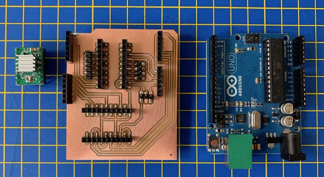
This board is basically just headers. And I think I may have already made some mistakes (in the wiring of the end-stop connection headers), so it’s unlikely to last in this form for long.
WIP I’m pretty sure the end-stop switch headers are incorrectly routed on this board. I should confirm it either way.