Testing the motor and driver
Having never used a stepper motor before, I started by trying to get my head around how these can be controlled via Arduino.
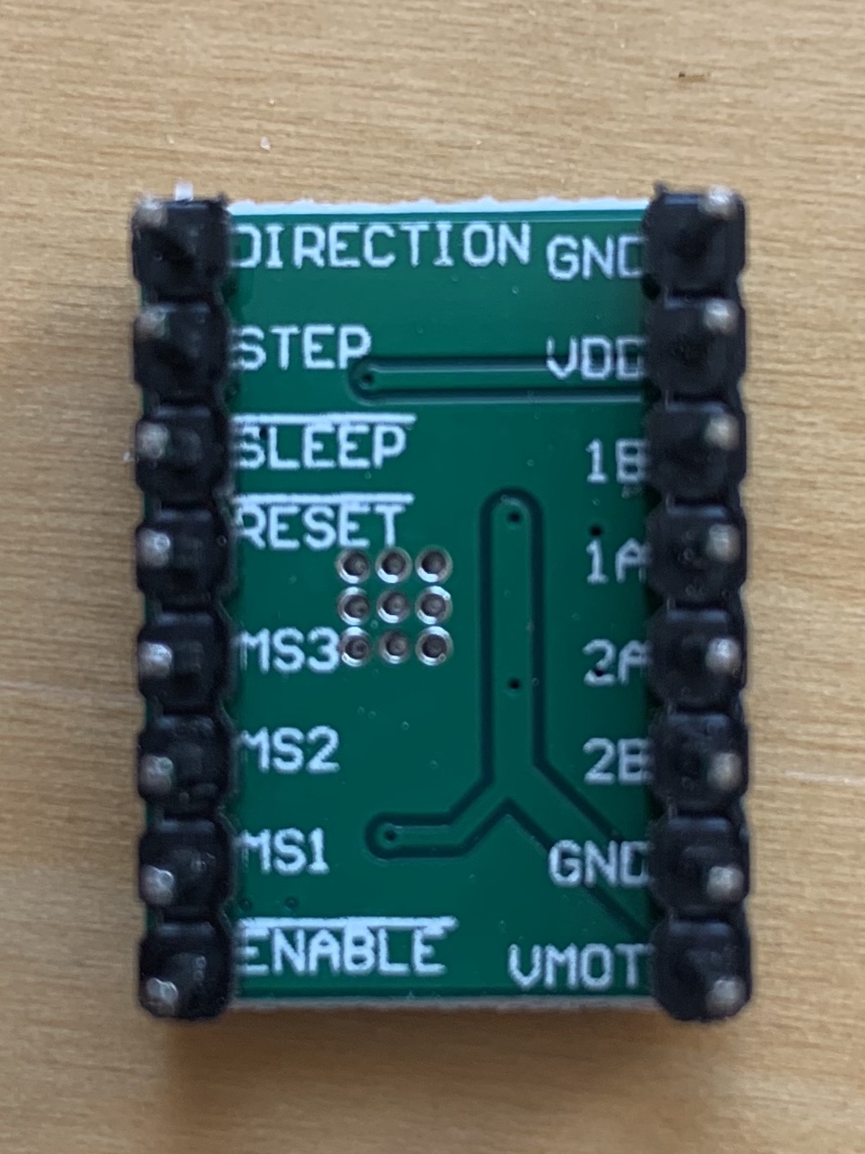
Driver board pinout
These boards have headers for connection to a breadboard (or carrier board). Unfortunately the pins are labelled on the underside, so it’s difficult to see what’s going on once you have it installed on a breadboard. In the end, I just connected wires directly from my Arduino and power supply to the male headers on the underside of the board.
SparkFun’s Big Easy Driver stepper motor driver(based on the same chip) has some nice documentation, so I wanted to use that to start experimenting with my motor. However the header pin arrangement and labelling on their board is slightly different, so I had to map one to the other. It was mostly pretty easy, except for the voltage pins (VDD and VMOT). So I had to do some digging on those:
The BigEasyDriver has a pin labelled M+:
M+ : This is the power input to the Easy Driver. Connect this to the positive power supply lead. This should be a 6V to 30V, 3A (or more) power supply that is clean (low ripple).
The datasheet has a V pin called VBB (2 in fact, which are shorted with a large 100uF capacitor). This is the “Load Supply Voltage“, rated up to 35 V. So I think VBB maps to M+. And on my board, the largest capacitor is near the VMOT pin, so I think this is the equivalent
The BigEasyDriver also has a pin labelled VCC:
VCC : This is an OUTPUT pin that will provide either 5V (default) or 3.3V from the voltage regulator, at a small amount of current (say 50mA - depends on input voltage) to power a circuit that you may need powered.
On the datasheet, I think this maps to the pin VDD, “Logic Supply Voltage“ (rated at –0.3 to 5.5 V). And I think this should map to VDD on my board.
The result:
Left side – viewed from the bottom – reading top to bottom
| DIRECTION | This needs to be a 0V to 5V (or 0V to 3.3V if you’ve set your Big Easy Driver up that way) digital signal. The level if this signal (high/low) is sampled on each rising edge of STEP to determine which direction to take the step (or microstep). |
| STEP | This needs to be a 0V to 5V (or 0V to 3.3V if you’ve set your Big Easy Driver that way) digital signal. Each rising edge of this signal will cause one step (or microstep) to be taken. |
| SLEEP | This normally high input signal will minimize power consumption by disabling internal circuitry and the output drivers when pulled low. |
| RESET | This normally high input signal will reset the internal translator and disable all output drivers when pulled low. |
| MS3 | These digital inputs control the microstepping mode. |
| MS2 | These digital inputs control the microstepping mode. |
| MS1 | These digital inputs control the microstepping mode. |
| ENABLE | This normally low input signal will disable all outputs when pulled high. |
Right side – viewed from the bottom – reading top to bottom)
| GND | There are three GND (Ground) pins on the Big Easy Driver. They are all connected together inside the board. Connect the negative side of your power supply; as well as from any other boards you are using to drive the Easy Driver to one or more of the GND pins. |
| VDD | This is an OUTPUT pin that will provide either 5V (default) or 3.3V from the voltage regulator; at a small amount of current (say 50mA - depends on input voltage) to power a circuit that you may need powered. |
| 1B | These are the motor connections. See below diagrams for how to hook these up. A and B are the two coils of the motor and can swap the two wires for a given coil (it will just reverse the direction of the motor). |
| 1A | (as above) |
| 2A | (as above) |
| 2B | (as above) |
| GND | (as GND above) |
| VMOT | M+ : This is the power input to the Easy Driver. Connect this to the positive power supply lead. This should be a 6V to 30V 3A (or more) power supply that is clean (low ripple). |
Safety
I’ve heard that it’s quite easy to fry a stepper driver (or even the motor itself). I’m not clear why, but it seems there are a few common causes:
Intermittent connections
One possible cause is disconnecting the motor (intermittently) while still providing power to the board. From the BigEasyDriver instructions, referring to the voltage out pins - 1A, 1B, 2A, 2B:
Make CERTAIN that this connection to the motor is solid, and NOT through a connector that has any chance of intermittent contact (which will fry the motor driver chip).
And from In-Depth: Interface A4988 Stepper Motor Driver Module with Arduino:
WARNING Connecting or disconnecting a stepper motor while the driver is powered can destroy the driver.
Voltage spikes
From In-Depth: Interface A4988 Stepper Motor Driver Module with Arduino:
According to datasheet, the motor supply requires appropriate decoupling capacitor close to the board, capable of sustaining 4A. WARNING This driver has low-ESR ceramic capacitors on board, which makes it vulnerable to voltage spikes. In some cases, these spikes can exceed the 35V(maximum voltage rating of A4988), potentially permanently damaging the board and even the motor. One way to protect the driver from such spikes is to put a large 100µF (at least 47µF) electrolytic capacitor across motor power supply pins.
At the moment, I’m driving the motor from the 12V VIN supply on my Arduino, which I believe has protection against spikes, however, this modification would be easy to implement on a dedicated power supply.
Allowing the motor to draw too much current
WIP Here’s something I don’t fully understand. It’s easy to blow an LED by allowing it to draw all the current it can – because it has no/low internal resistance. I don’t know if limiting the current to a stepper motor works the same way.
However, it is possible to limit the curent to the motor to within its safe limit using the trimmer potentiometer on the driver board.
Adjusting current draw
Many explanations of these driver boards talk about the need to adjust the current draw using the small trimmer potentiometer. My board even came with a tiny screwdriver for just this purpose.
My initial attempts to do this were physically a mess (it’s difficult to connect everything up) and the results were difficult to interpret. (Turning the trimmer seemed to affect the current draw in inconsistent ways, with none of the readings making any sense, given the data I do know about the motor, power supply and so on.)
Eventually I found some good instructions on the Pololu site:, and a very good video, and I managed to get some sensible readings from my multimeter.
The process I followed
Determine the amount of current you want to use to run the motor: Mine is 1.68A/phase
Choose a driver with a max current rating higher than the current you want to use to drive you motor Then limit the current to below the max rating of the motor. My A4988 driver board is rated at up to 2A per coil
Then, use the current limit calculation for your driver to calculate the appropriate VREF voltage setting . Mine is a Stepstick clone. From StepStick - RepRap:
To calculate the current, A = VREF / (8 * RS). For a standard stepstick, RS is the rating of the Sense Resistor = 0.2ohm. So A = VREF / 1.6 To calculate the VREF for a target current, VREF = A * 8 * RS , or A * 1.6 . So, if you wanted 0.8A, VREF = 0.8 * 1.6 = 1.28V
However, RS on my boards is a different value. It’s marked R100 – ie 0.100Ω, so for these boards
VREF = A * 8 * RS
= 1.68 * 8 * 0.1
= 1.344 V
From StepStick - RepRap:
There is a test point for VREF on the Pololu but it is missing on the Stepstick. Since it is just the wiper of the pot you can measure it there and it is easier as it is a bigger target. I hold the positive meter probe on the shaft of a metal screwdriver so I can see the value while I am turning the pot. Put the negative probe on a ground pin.
- By clipping the positive meter lead to a screwdriver and adjusting the trimmer pot, I can get a range of 0 - 1.12V. All within the limit of my motor.
Making use of the 70% current headroom?
As per the A4988 datasheet, on full step mode, the driver only sets the coil current to 70.71%, however, if you use micro-stepping mode, as I intend to, it does use 100% of the current on some steps, so this gives me no room to increase the current more.
Simple programs
There are many simple stepper programs that make the motor turn, without the use of libraries or the motor’s special modes.
Here’s one:
/*     Simple Stepper Motor Control Exaple Code
 *  by Dejan Nedelkovski, www.HowToMechatronics.com
 */
// defines pins numbers
const int stepPin = 3;
const int dirPin = 2;

void setup() {
  // Sets the two pins as Outputs
  pinMode(stepPin,OUTPUT);
  pinMode(dirPin,OUTPUT);
}
void loop() {
  digitalWrite(dirPin,HIGH); // Enables the motor to move in a particular direction
  // Makes 200 pulses for making one full cycle rotation
  for(int x = 0; x < 200; x++) {
    digitalWrite(stepPin,HIGH);
    delayMicroseconds(500);
    digitalWrite(stepPin,LOW);
    delayMicroseconds(500);
  }
  delay(1000); // One second delay

  digitalWrite(dirPin,LOW); //Changes the rotations direction
  // Makes 400 pulses for making two full cycle rotation
  for(int x = 0; x < 400; x++) {
    digitalWrite(stepPin,HIGH);
    delayMicroseconds(500);
    digitalWrite(stepPin,LOW);
    delayMicroseconds(500);
  }
  delay(1000);
}
And this demonstrates the most basic functions of the driver chip: to set direction, and speed:
Control Spinning Direction: To control the spinning direction of a motor we set the DIR pin either HIGH or LOW. A HIGH input spins the motor clockwise and a LOW will spin it counterclockwise.
Control Speed: The speed of a motor is determined by the frequency of the pulses we send to the STEP pin. The higher the pulses, the faster the motor runs. A pulses is nothing but pulling the output HIGH, waiting a bit then pulling it LOW and waiting again. By changing the delay between two pulses, you change the frequency of those pulses and hence the speed of a motor.
Initial problems
Floating RESET pin
Initially, when I tried this code, nothing happened, except a slight grinding noise when I jiggled the board around, or moved my hand close to it. After, some digging, I found this bit of essential advice:
The RST pin is floating. If you are not using the pin, you can connect it to the adjacent SLP/SLEEP pin to bring it high and enable the driver.
Floating pins are a familiar source of unreliable input. If you’ve ever tried to wire up a simple button to an Arduino and had it behave seemingly randomly, you’ve experienced this. In particular, just moving your hand close to the board can be enough to change the voltage on the pin. So I suspected this might be the problem, and sure, enough, when I connected together RESET and SLEEP, my demo Arduino sketch worked fine.
Adjusting current
As noted above, for some settings of the current trimmer, the motor seemed to move unreliably, or with a lot of noise or vibration. I tried turning the trimmer (I don’t know which way is ‘up’) and that seemed to help.
AccelStepper Arduino library
Then I went looking for a library that would let me control the motor easily without having to write code to pulse the STEP pin manually. Arduino has a built-in stepper library, but I also found the AccelStepper library, which seems to be more fully-featured, though lacking in much basic documentation beyond the class/function reference, which is not very helpful when you’re getting started.
You can install this library, with examples, through the Arduino Library Manager.
Here’s the basic sketch to get the motor turning at a set speed:
// ConstantSpeed.pde
// -*- mode: C++ -*-
/// \author  Mike McCauley (mikem@airspayce.com)
// Copyright (C) 2009 Mike McCauley
// $Id: ConstantSpeed.pde,v 1.1 2011/01/05 01:51:01 mikem Exp mikem $

#include <AccelStepper.h>

AccelStepper stepper(AccelStepper::FULL2WIRE, 3, 2);

void setup()
{
   stepper.setMaxSpeed(1000);
   stepper.setSpeed(150);
}

void loop()
{
   stepper.runSpeed();
}
Note the parameters passed to the constructor function. The default format is:
AccelStepper stepper;. By using the format, AccelStepper stepper(AccelStepper::FULL2WIRE, 3, 2); I’m specifying a particular kind of motor (perhaps incorrectly…) and setting pin 3 to be the STEP pin, and 2 to be the DIRECTION pin.
There is some useful explanation here:
So the first parameter is the interface type, and is one of the types listed (1, 2, 4, 6 or 8), and the parameters after that define the actual pins that are wired up. The examples don’t show anything except the default way of accessing the object, without any parameters at all, which maybe doesn’t help.
AccelStepper stepper(1, 3, 2);is synonymous withAccelStepper stepper(AccelStepper::DRIVER, 3, 2);which might make a bit more sense.The above means that the stepper object is created, interfaced to a hardware stepper motor driver (like a DRV8825) using two wires from arduino pins D3 and D2.
Again looking at the docs, for the constructor, pin1 (defined as D3 in your example) is the step input to the driver and pin2 (defined as D2 in your example) is the direction input to the driver.
Problems
Noise and vibration
That worked, but it was super noisy. (I think this is due to the STEP pin being pulsed…) I tried using the micro-step functions and increasing the speed to compensate, however, after turning this up to, I think 6000, my motor stopped working. I ordered some new drivers, which did work, so I can only assume I fried the driver board.
Stopping the motors using the stop() function
I also tried simulating the effect of the gantry hitting the end-stop switch:
void loop()
{
   stepper.runSpeed();

  // while the button is pressed ...
  while (digitalRead(buttonPin) == HIGH) {
   stepper.stop();
  }
}
While this worked, I found that after I released the button the motor didn’t start properly again, just grinding without moving.
I got around this by not using the stepper.stop(); function, and instead putting the stepper.runSpeed(); function inside a conditional. But it would be good to understand the cause of the problem. WIP
Purpose of setMaxSpeed() function
WIP
I don’t know why this is in the example code. If it’s made redundant only by the use of the runSpeed() function instead of run(), why is it in the example code?
FULL2WIRE parameter in AccelStepper constructor
Have I used this incorrectly? My motor does have 4 wires… I think when I set this I may have been confusing the control wires (STEP and DIRECTION) and the motor coil wires.
I wonder if this is causing some of the problems I’m having… WIP