Version 1 – The good, the bad and the ugly
I’ve got to a pretty good place with version 1 of my slider. I have a functioning product, that does pretty much what I set out to do (with one big caveat - see below). And I also have a long list of improvements I’d like to make for version 2. So now’s a good time to draw a line under version 1, and reflect on the process and results.
The good
Learning about 3D printing and driving motors
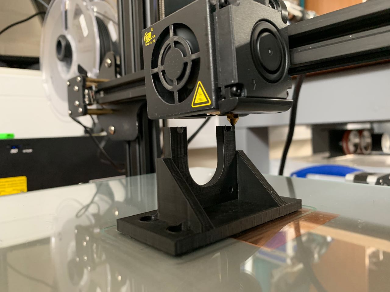
A lot of the good things are about the process more than the machine itself. Two things I wanted to explore more, and I really enjoyed it. I loved designing the 3D parts, and spending more time in Fusion 360. This is becoming more of a creative environment fr me know, and less of a chore. The Creality CR10 printer I used was great. A real workhorse, and most things pretty much ‘just worked’.
Stepper motors were a big grey cloud of uncertainty when I started. I didn’t really know how they worked, how to choose one, or how to drive it. Now I’m much more confident in this area. One thing I’ve seen on the horizon, but not touched yet, is Grbl. I’d like to find an excuse to look into this some more.
Doing more with Arduino, state machines
My Arduino skills are slowly bedding in. I did a lot of research into state machines, and found this model to be immensely helpful, even though I ended up simplifying my state machine drastically from the original idea.
Documentation
I’ve written a lot of documentation for this project! Maybe even too much. But I think the process has helped me be more systematic and rigorous in my work.
Arduino Shield
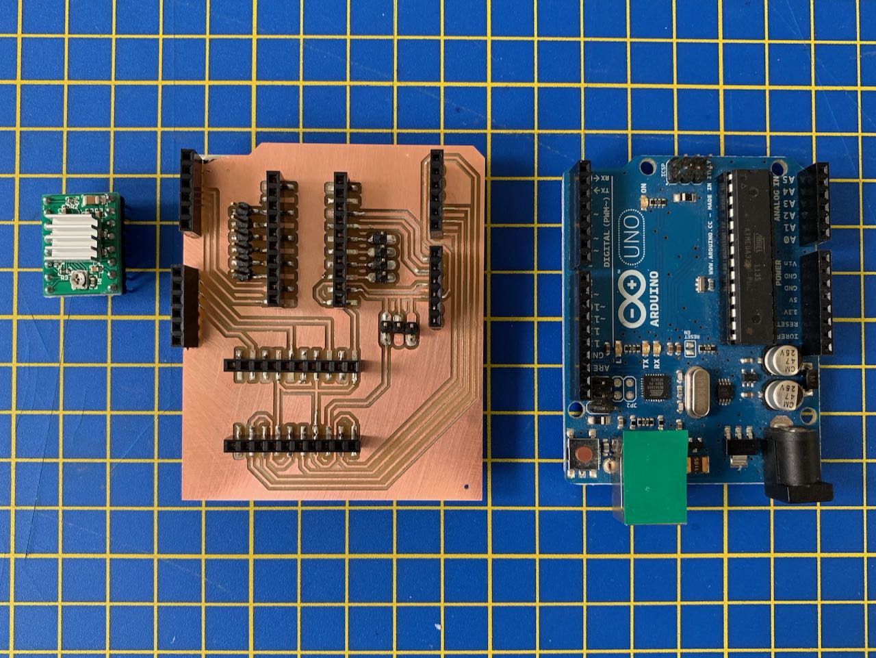
Like Fusion 360, Eagle is frustrating software for the uninitiated. But as I get more comfortable with it, I find it very rewarding. I’m quite pleased with my simple driver shield, and think it supports the project aims of being easily replicated by others.
Architecture
I settled on this architecture:
- Widely available commodity machine parts (aluminium extrusion, M5 fixings)
- Commodity motor control electronics (cheap A4988 stepper driver boards)
- Stock Arduino Uno microcontroller
- Easily fab-able parts: driver Arduino shield, 3D-printed gantry and brackets, laser-cut end caps
I think this strikes a good balance between building everything yourself, and making use of affordable manufactured parts. It’s not simply piecing together a kit, nor is it DIY as a form of punishment. There are plenty of opportunities for learning, and for optimisation in design and making, and by version 2, I think I will be able to make a well-integrated product that could feasibly by used in a production environment.
There are other ways of doing the electronics for this project, but I think the approach of Arduino Uno + DIY shield + cheap commercial driver board allows for a good mix of replicability, cost-effectiveness and accessibility.
Potential student project
I think this could be a great student project, with plenty of room to learn about motion control, machine building, software, assembly, materials, and perhaps most importantly, quality, which I’ll come back to later.
As a challenge for students, it could also be generalised slightly to be a ‘one-axis CNC machine’, which would allow for lots of interpretations (from a drawing robot to a drinks dispenser) so students could make something that really appealed to them.
The bad
Integration
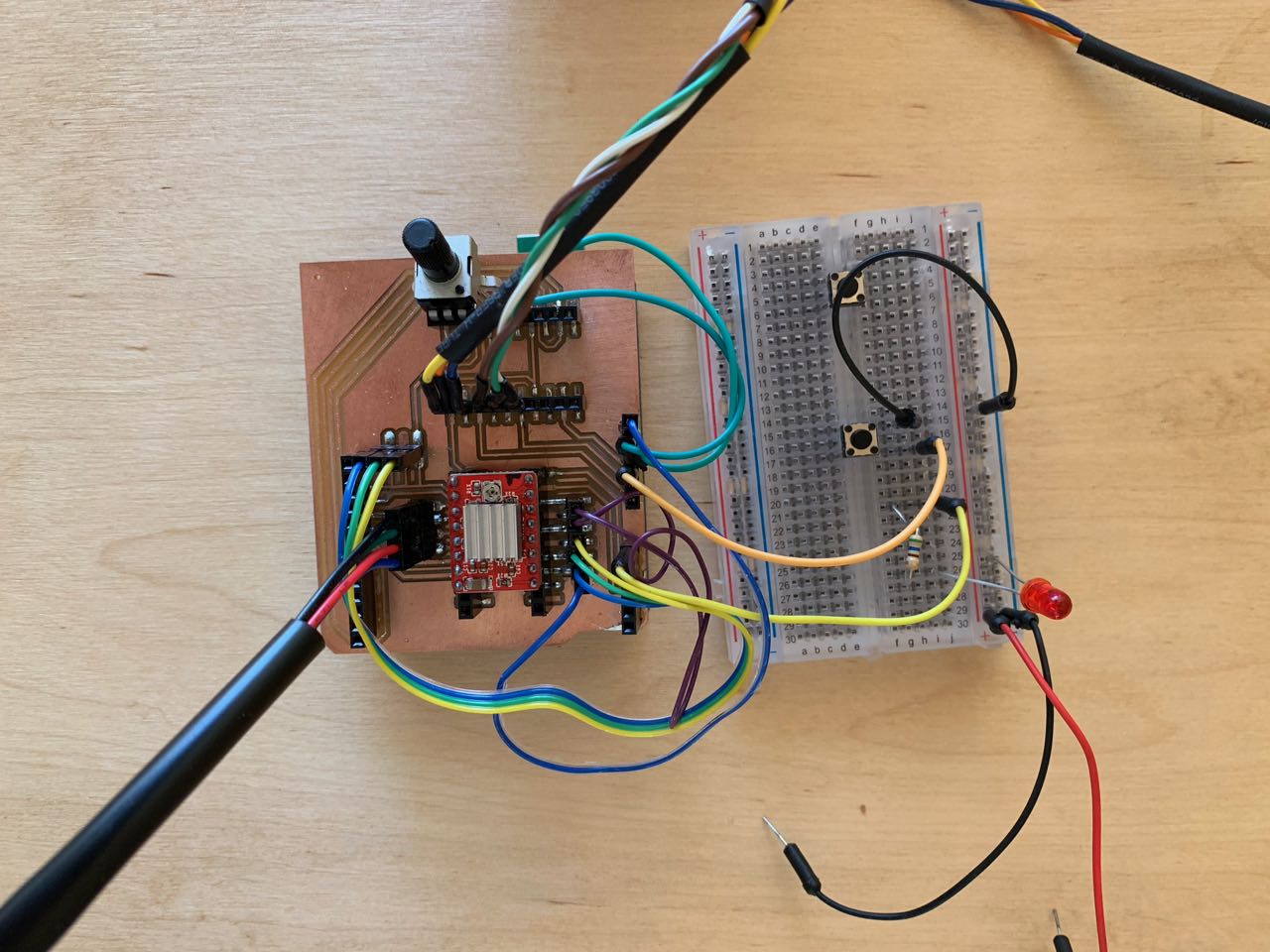
The electronics are still loose, with a breadboard, jumper wires and other bits and pieces all dangling precariously. Clearly this needs a case. Once I’ve enabled the motor issues, this will be a key part of the version 2 build.
Driver shield improvements
I’ve already designed a much better Arduino shield to hold the stepper driver board. That would be a straight drop-in replacement for the one I’m using now. However, I’m putting this on hold until I’ve decided what motor and driver combination to use for version 2.
Construction dependencies
I need to do some more experiments with different kinds of V-slot fixings. Threaded holes in the ends are the most mechanically sound, but unless you’ve got good quality taps and you know how to use them, it’s easy to mess up tapping holes. Many machines like this rely on right angle brackets, specialised v-slot nuts or 3D-printed mounts that mate with the v-slot profile.
This needs more experimentation, but I’d like o find a way to build this without depending on threaded holes in the ends of the extrusion.
Industrial design niggles
I noticed a few problems with the industrial design and construction, which I’ll need to look at workarounds for:
- The right-angle brackets at the read end coming loose
- The idler pulley interferes with the rear end cap
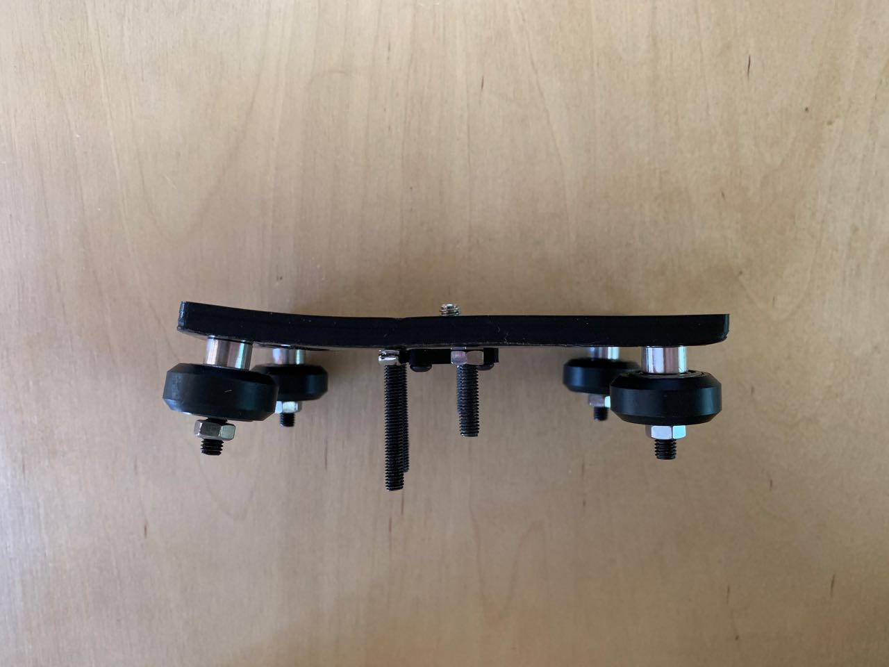
- The bolts securing the camera D-ring capture plate from underneath interfere with the timing belt
- The end-stop switches are difficult to mount: there is no easy way to access the fixing bolt once the bracket is on the rail
- The gantry currently has two bolts designed to hit the end-stop switches at the end of the traverse. I ghoul die able to get away with one.
Melting PLA
I’m currently in a hot climate (daytime temperatures up to 35 °C) and that seems to have partially melted one of my PLA parts. As far as I understand, PLA shouldn’t start to become plastic until about 60 °C, so I’m not quite sure how this happened. Nevertheless, I may need to look at alternatives: either printing in ABS, or avoiding 3D printed parts altogether (I was able to replace the gantry with an alternative 2-part glued version I laser-cut from MDF).
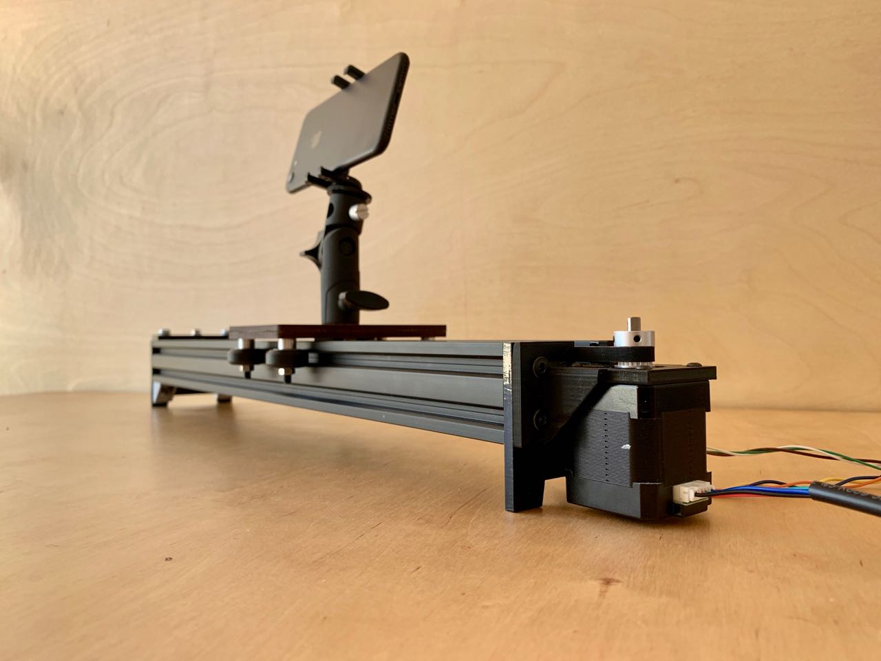
In use
This version is designed to sit on a table with the camera directed out from the slider, also horizontally. By using an adjustable tripod mount, you can also have it point slightly up, down or whatever. However, I soon found that a very useful orientation for filming is top-down. For example, mounting the slider above a work area filming a process from above. There’s no easy way to do this with the current design.
In this use case, having a way to position the slider on its side, or mount it on a vertical surface would be useful.
When using it outside, flat, horizontal surfaces are hard to come by. So here, adjustable feet or a tripod mount would also be good features. Although I’m skeptical about how stable something this heavy would be on a tripod. Even just more widely-spaced feet would help.
And something which I considered at the beginning – but which I never intended to put in version 1 – is some form of target tracking, even just an approximate angling of the camera towards the centre point as it makes its traverse.
The ugly: vibration
I had always been concerned about vibration form the stepper motor. I’m using 1/16th micro stepping to limit this, but even in this mode, there is considerable visible camera shake caused by vibration in the system.
For m, this is a question of quality. As a DIY maker project, it’s about 90% there. But that last 10% is just as important. And likely just as difficult. But I don’t want to make an OK slider; I want to make a really good one.
After doing many tests, I’ve identified a number of factors which seem to contribute, aside from the vibration from the stepper motor. In particular, anything which causes camera instability regardless of whether the motor is running:
- Wind, when using outside
- Filming with a phone mounted in a phone tripod mount, instead of a heavy, flat-bottomed SLR-style camera mounted straight to the gantry
- Adding an adjustable tripod adapter to enable positioning, which amplifies any motion
But the killer is automatic optical image stabilisation (OIS), which at least on my phone, can’t be switched off. I was able to test the slider with an iPhone XR (automatic-OIS) and an iPhone 6s (no OIS) and the difference is remarkable:
Clearly the OIS system is really thrown off-kilter by the vibrations from the motor. However, even the non-stabilised footage form the 6S is too shaky to make the grade. It’s not so noticeable when shooting time-lapses, although again, using the iPhone’s built-in time-lapse camera mode, the OIS effect is pretty bad.
It’s much better with a real camera, but I want this machine to be usable with a phone. So this is something I need to address.
Options
I might be able to get one more level of Microstepping (down to 1/32 of a step) by using a different driver (a DRV8825 instead of an A4988). I’m looking into this:
Stepper Driver Noise: A4988 vs DRV8825 (Updated) - YouTube
I’m also researching DC motors, which might be more suitable than the stepper I’m currently using.
There might also be mounting or construction techniques I can use that will minimise vibration throughout the system, and in particular stop It being amplified by the time it gets to the camera.
Wishlist for version 2
So that leaves with a nice list of things to try for my next version:
- A different motor, or a way of driving the stepper with less vibration
- Design and construction for damping of vibrations
- Different mounting options: tripod, on its side, attached to a vertical surface
- Integrated housing and tidy internal cabling for all parts: no breadboards or loose jumper wires
- Industrial design that doesn’t require tapped holes in the extrusion
- Better feet for stability outside in wind or on uneven surfaces
- ABS printing of plastic parts
- Improvements to the pulley and end-stop mounting, and gantry end-stop bolts
- A revised driver shield board
And some things that I might bump to version 3, if I get that far:
- A smaller version, maybe using a smaller motor and only one rail, to reduce material usage, cost, size and weight (perhaps one that could be powered from a 5 V USB power supply, or 3.7 V LiIon/LiPo battery for portable use)
- Wireless control over bluetooth or wifi via a smartphone app (of course, ideally this would integrate control of the camera on the phone as well!)
- A simple GUI on an OLED screen to show basic parameters such as speed, mode and direction