Designing new stepper driver and controls boards
While the fundamental design (of an Arduino shield to holder the stepper driver and provide an easy way to connect controls) was sound, there were a lot of improvements I wanted to make to version 1 of the shield. These notes merge together many changes that in reality were implemented in incremental steps between v.1 and v.2.
Board-mounted controls
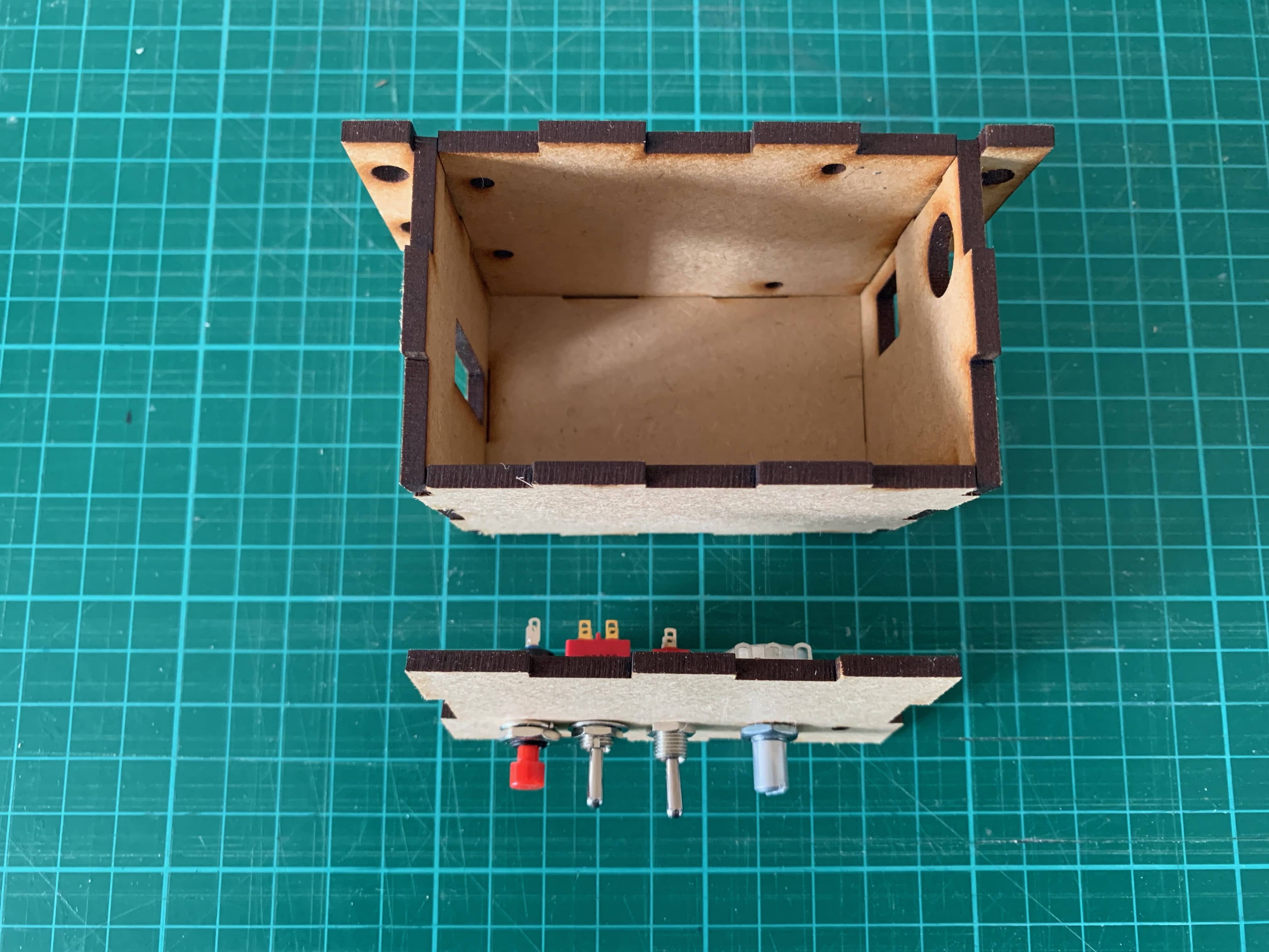
In early prototypes, I tried using panel mounted controls, which would be connected by wires to headers on the board. This would enable me to assemble the case with he board inside, fit the controls to the panel , then bring the two parts together. However, I’ve never liked that approach. It’s messy, with loose wires everywhere; introduces complexity (needing headers to connect parts); and feels like an inelegant hack.
This early prototype case shows how I thought I could mount the controls.
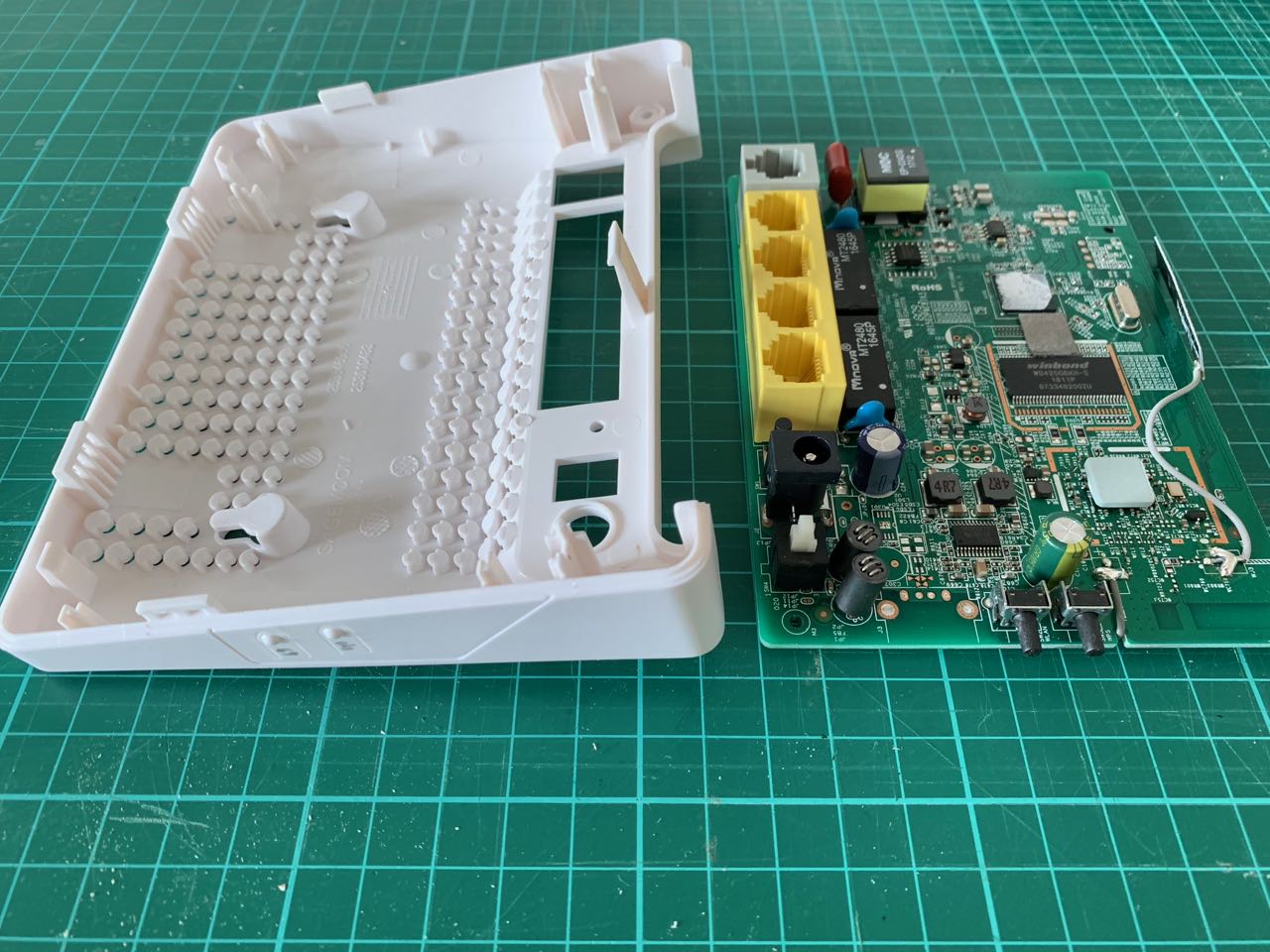
In contrast, many commercial products use board-mounted controls, which are either exposed directly to the user through holes in the case (like the ethernet sockets, DC socket and power switch on the left side of this circuit board from a router) or indirectly through a flexible membrane (as often seen on keypads) or a flexure in the plastic case (as in the two side-mounted buttons on the front edge of this router board)
So I decided to emulate this approach, and try to mount all the controls on the boar, and expose them through holes in the casing.
Splitting the board into two
This introduced a new problem - the vertical space taken up by each component becomes a critical factor. I want all the exposed controls to protrude outside the case, the display to be safely inside, and all other parts to be tucked out of the way.
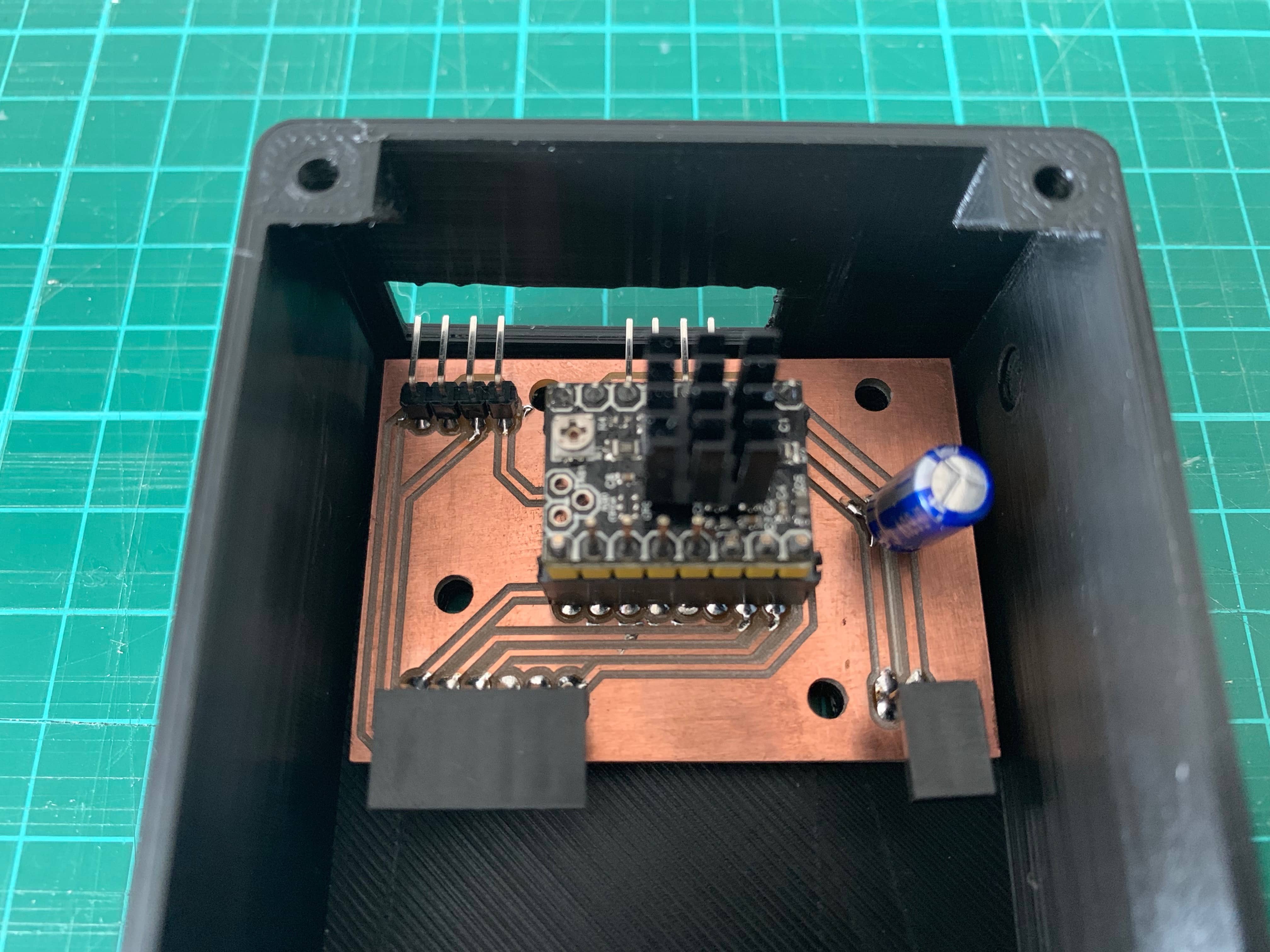
The driver itself is very tall: it includes a heat sink, and needs to be mounted on headers (or soldered permanently to a board). So I needed to move this to a separate board so it could be mounted out of the way.
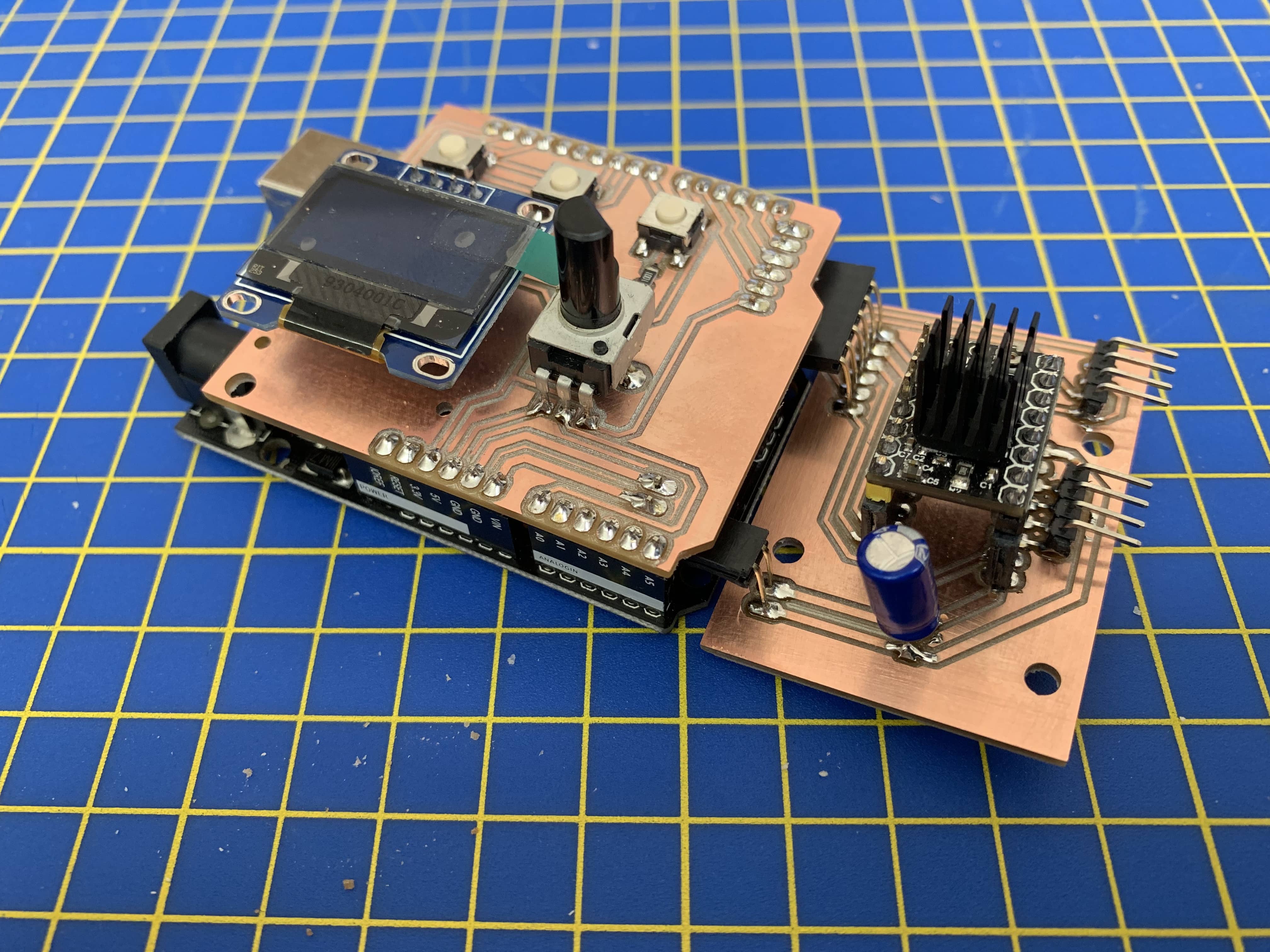
In this photo the boards are connected directly by headers mounted at right angles on the edge of each board. But in later versions these are connected by a ribbon cable. This board also has standard short SMD buttons, but I subsequently bought some taller buttons that are closer in height to the potentiometer.
Simplifying headers
Version 1 of this board is mostly just headers. I was able to simplify it greatly by changing the way I handled most of these:
Male Arduino mounting headers
Instead or using female ’stacking’ headers to mount to the Arduino IO and power pins, I just used male headers mounted to the underside of the shield. The plastic frame give the shield just the right standoff to clear the USB and power sockets. The tradeoff is that I can’t connect anything through these headers to the Arduino pins. But as I’m doing all the routing I need anyway on the shield itself, this isn’t a problem.
Controls
I had more female headers set up to plus in LEDs, switches, potentiometers, end-stops and buttons. As noted above, I eventually decided to mount almost all of these directly for the board, so I could get rid of almost all of these (except the end-stop connection points which still still need to be exposed to a header)
Swapping SMD for through hole
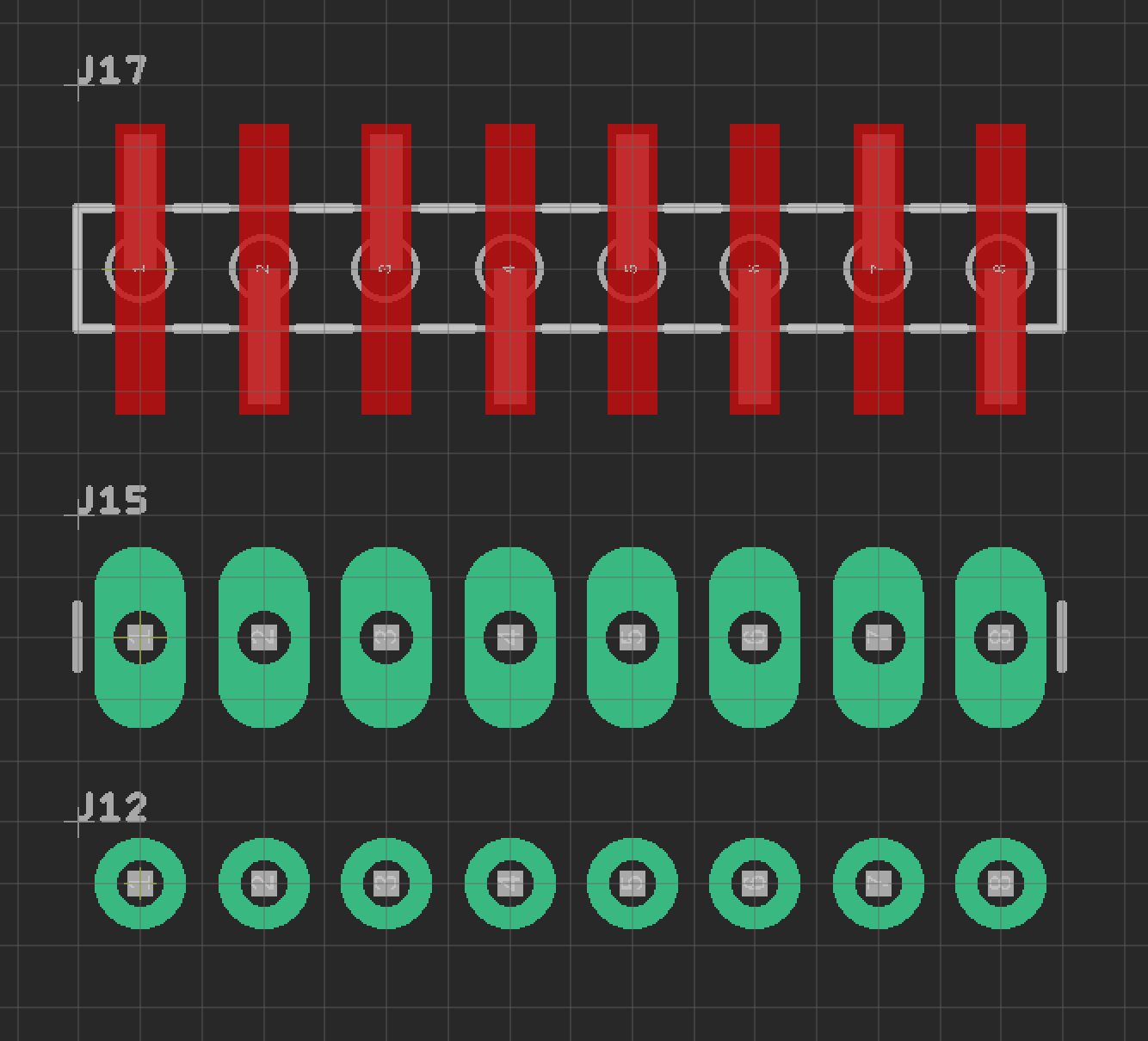
I have access to some 10-pin female headers with SMD mounting pins. These are perfect for mounting on milled boards, as no drilling is required. But they’re expensive, and I don’t always need 10 pins on a header. The splayed feet arrangement means they also take up a lot of space on the board (J17 in the screenshot from Eagle below).
After running some tests, I was able to confirm that I can safely drill 1.1 mm holes on the milling machine, making through-hole mounting viable.
I settled on the ‘long pads’ variant for through hole headers (J15 in the screenshot below) to make it easier to flow solder under the headers. (It can be tricky because in most cases you’re soldering on the ‘wrong side’ of the board, and the plastic casing gets in the way)
Connection points for motor and end-stops
The motor and the two end-stop switches are not contained within the electronics housing, so I needed to expose pins so these could be connected from outside. This photo shows those two 4-pin headers and the hole in a prototype case through which they can be accessed.
Routing for TMC2130 stepper driver
As I’m not using the SPI functionality of this board, routing is actually easier than the A4988. Many of the pins can be left floating – i.e. unrouted.
My board is a cheap clone of a breakout board by Watterott (which is what I would buy if I was buying another)
- Docs for the ‘SilentStepStick’ breakout board: Pinout and Powering - SilentStepStick - Watterott electronic
- Docs for the TCM2130 chip: TMC2130 - Trinamic
SilentStepStick Pinout
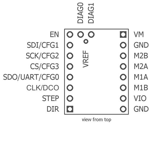
- EN, STEP, and DIR are routed to Arduino digital IO pins. I picked the pins to give the easiest routing when also considering the other signals that needed to go to the Arduino digital IO. All the other pins on the left side are left floating.
- GND is routed wherever it’s needed.
- The 4 motor pins just go straight out to the motor (via a male header)
- VMOT comes from VIN on the Arduino. And I added a capacitor here to smooth power. Power from VIN on Arduino is unregulated.
From In-Depth: Interface A4988 Stepper Motor Driver Module with Arduino
According to datasheet, the motor supply requires appropriate decoupling capacitor close to the board, capable of sustaining 4A. WARNING This driver has low-ESR ceramic capacitors on board, which makes it vulnerable to voltage spikes. In some cases, these spikes can exceed the 35V(maximum voltage rating of A4988), potentially permanently damaging the board and even the motor. One way to protect the driver from such spikes is to put a large 100µF (at least 47µF) electrolytic capacitor across motor power supply pins.
See also What Are Decoupling Capacitors in 5 Minutes
OLED screen
I decided to add a small I2C OLED display, so I could show the selected speed, mode, direction, and any error messages. I already had 4 I2C pins exposed for this in the previous version of the board. However, they would have been connected by a cable, and I was also using the SDA and SCL pins on the Arduino Uno’s analogue IO header. The Leonardo, which is otherwise pin-compatible, doesn’t have SDA and SCL on this header, so I switched this to use the SDA and SCL pins on the digital header up by the USB port.
Progress
This photo shows the v.1 shield on the left, and the two-part v.2 shield on the right
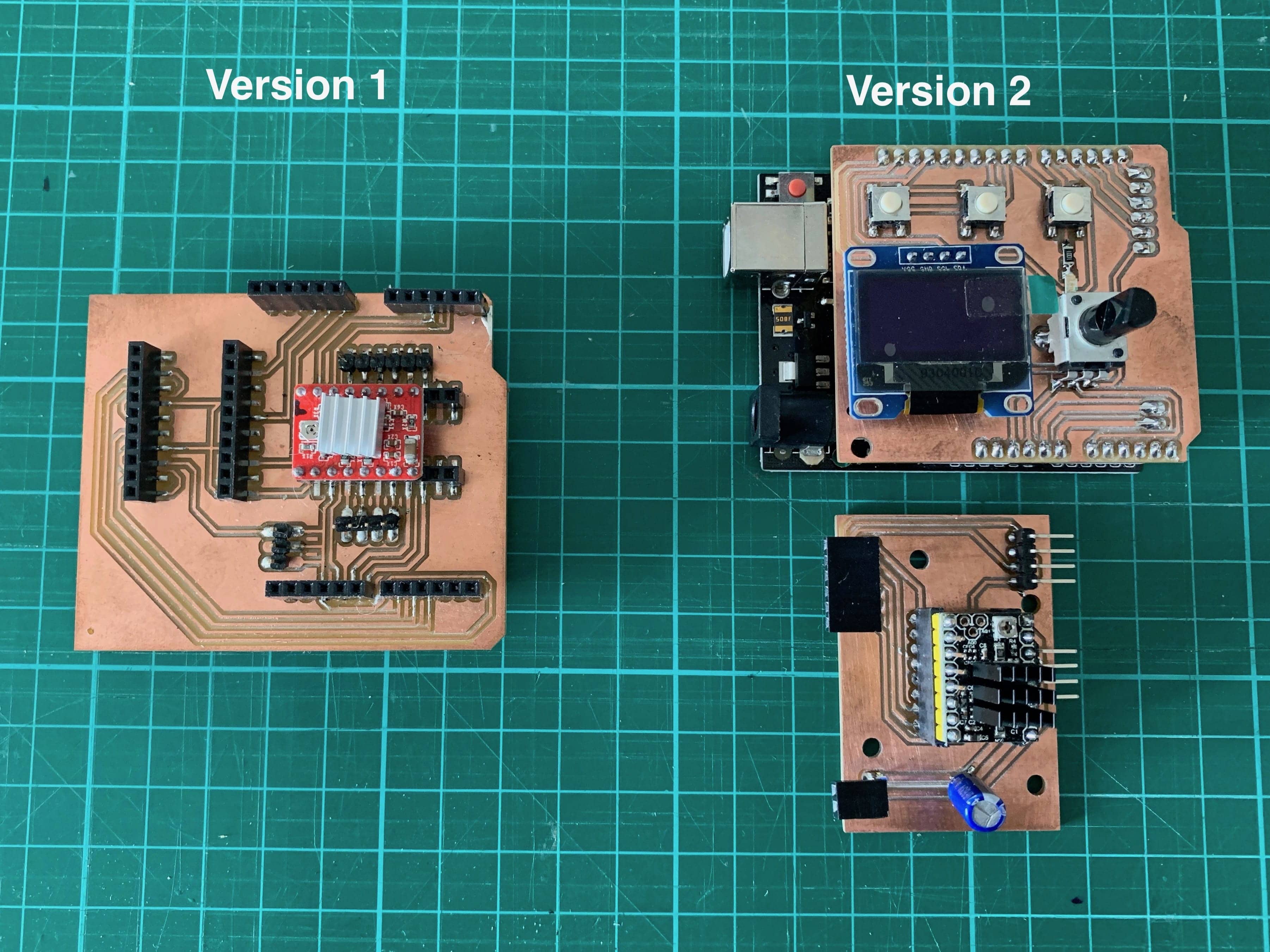
These board designs are all the the Git repo: fab-slider/boards/driver-arduino-shield/v2