Addressing vibration with a different stepper driver
My biggest problem with version 1 was the vibration coming from the stepper motor, and being transferred through the drivetrain to the camera. With modern iPhones’ non-optional optical image stabilisation, I was getting vary bad results from the small – but very inorganic – vibration motion.
I figured there were three avenues I could explore:
- Using a brushed DC motor instead of a stepper
- Mechanical fixes
- Using a different stepper driver
Experimenting with DC motors
I thought this might be an option, as one of the commercial sliders I’m aware of uses a DC motor: Ratrig V-Slider DIY Camera Slider kit
I didn’t go to far down this path as I didn’t want to shell out for a new DC motor, and the ones I had to hand weren’t ideally geared for this job.
I did manage to blow my Arduino trying to drive a DC motor directly, so I ordered a replacement and a L298N driver and had some limited success following this guide: Arduino DC Motor Control Tutorial - L298N - PWM - H-Bridge - HowToMechatronics.
However, with the motors I had to hand, there was too much whining. I’m guessing this is probably because they expect a 24 V supply, but all I have to hand is 12 V.
Mechanical fixes
I haven’t tried any of these out yet, but some digging turned up a few ideas of things to try:
From How do you minimize stepper motor vibration? - Electrical Engineering Stack Exchange:
… fundamentals of eliminating resonance and buzzing in mechanical subsystems is raise the resonant frequency with a stiff chassis and decouple with elastomer shock mounts to attenuate structure resonance or if not possible, then add viscous dampening.
And:
In my research, I came across a belt tensioner (spring loads belt) to help dampen the step pulse. If you are using a belt this could help. To reduce vibration: 1 add mass - such as a flywheel, etc. 2 insulate - use third party to deliver power 3 reduce force - lower current, microstep or (In my case add a spring belt tensioner) many others ways to reduce force. 4 tuning - run motor at higher speeds with reduction if applicable 5 dampen - such as a “shock absorber”, could be like a spring belt tensioner with shock
From How to Take Vibration out of Stepmotors - Machine Design:
Shift the resonance frequency by changing current or voltage, inertial load, or step resolution.
From Stepper motor vibration/resonance etc..how to elliminate?:
It might be necessary to fill the alloy sections with some dampening material with a high modulus such as stiff silicon rubber or an epoxy cement based material, Adding webs would also raise the stiffness and hence reduce any mechanical resonance in the axis track.
Using a different stepper driver
So far, this is the route I’ve pursued the furthest.
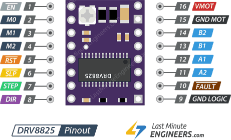
DRV8825
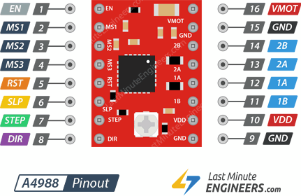
This is a common alternative to the A4988. The breakout boards are pretty much pin-compatible, and it offers one more level of micro-stepping: down to 1/32 step. I didn’t choose this driver as there was a better alternative, but I did find some useful resources:
General information: Pololu - DRV8825 Stepper Motor Driver Carrier, High Current
Comparison to older A4988: A4988 vs DRV8825 Chinese Stepper Driver Boards - RepRap
DRV8825 Pinout: In-Depth: Interface DRV8825 Stepper Motor Driver Module with Arduino
Compared to A4988 Pinout: In-Depth: Interface A4988 Stepper Motor Driver Module with Arduino
TMC2130
This driver was recommended to me by Ooznest. It has a load of nice features for more advanced stepper control, but the chief benefit of interest to me is 1/256 resolution micro stepping. Which they call “stealthChop”…
From the datasheet (p39):
stealthChop is an extremely quiet mode of operation for stepper motors. It is based on a voltage mode PWM. In case of standstill and at low velocities, the motor is absolutely noiseless. Thus, stealthChop operated stepper motor applications are very suitable for indoor or home use. The motor operates absolutely free of vibration at low velocities. With stealthChop, the motor current is applied by driving a certain effective voltage into the coil, using a voltage mode PWM. There are no more configurations required except for the PWM voltage regulator response to a change of motor current. Two algorithms are provided, a manual and an automatic mode.
The driver can be controlled over SPI, or by pulling config pins high or low. For the basic features I need, SPI is overkill, and in fact, I can leave most of the configuration pins floating and it defaults to the setup I need.
SPI mode is set by soldering (or desoldering a jumper on the board. The default state for this jumper is different on different boards. I have a particularly poor version, the BIGTREETECH TMC2130-V1.1. However, there is a manual, in Chinese, which says:
Q:驱动选择了 SPI 模式,但又想用回 STP/DIR 工作模式,怎么 办?
A:将 CFG4 和 CFG5 的连接断开,再把 R5 的两个焊盘连接起 来,如下图红色部分需要焊接,红框内不连接
Translated:
Q: The driver selected the SPI mode, but want to use the STP/DIR working mode. What should I do?
A: Disconnect the CFG4 and CFG5, and connect the two pads of R5. The red part of the figure below needs to be soldered, and the red frame is not connected
This is in fact how the module comes, so no soldering is needed on these tiny pads.
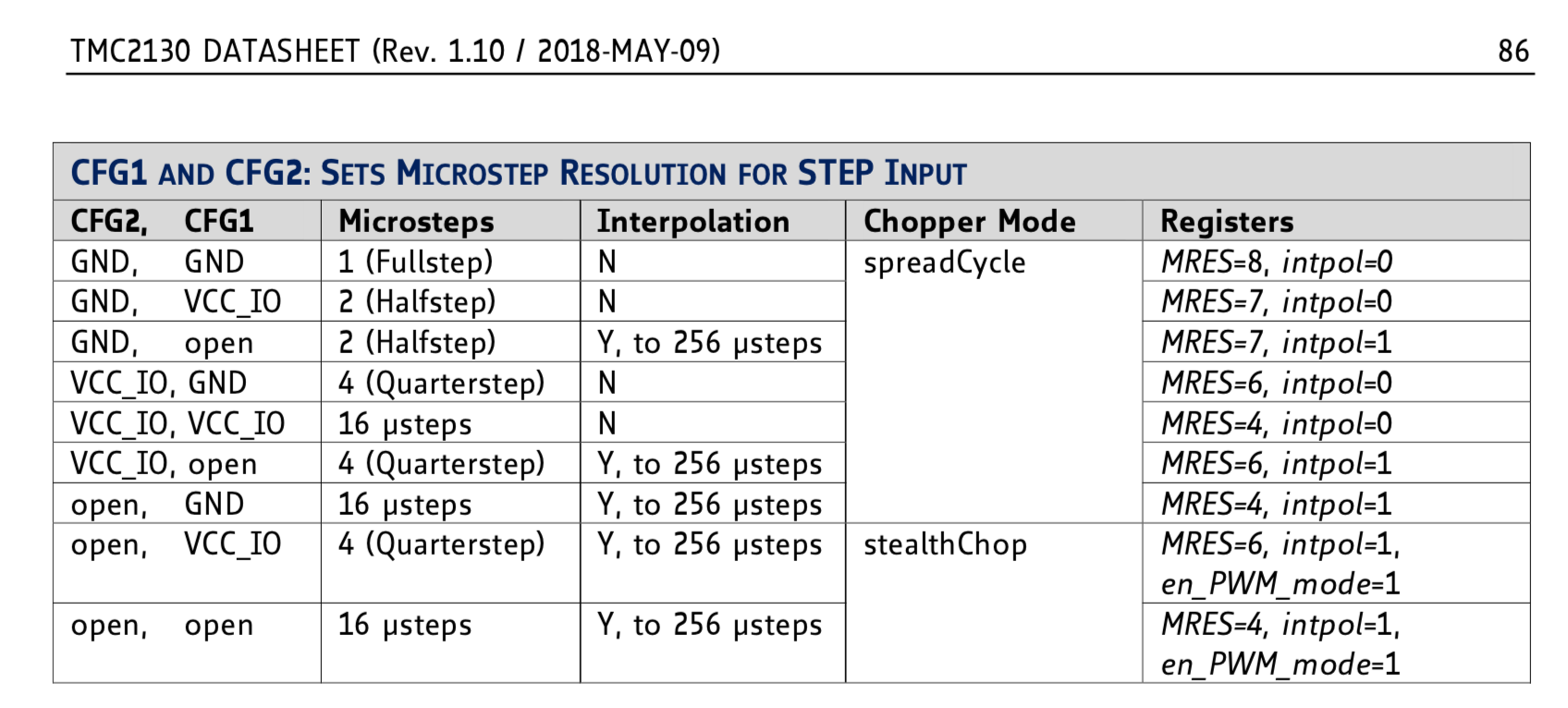
There is an explanation of how to use the config pins (when not using SPI mode) in the TMC2130 datasheet:
24 Standalone Operation For standalone operation, no SPI interface is required to configure the TMC2130. All pins with suffix CFG0 to CFG6 have a special meaning in this mode. They are evaluated using tristate detection, in order to differentiate between CFG pin tied to GND CFG pin open (no connection) CFG pin tied to VCC_IO
I also found this video helpful: TMC 2130 Stepper Drivers - Standalone Mode - Chris’s Basement - YouTube
The upshot is that I was able to design a new driver shield board with very minimal changes to accommodate the different pinout of this driver. These changes are described on the page for the new shield design.
So far, the results have been very good.