DIY Photo Lightbox
My first attempt at making my own lighting gear for project photography. Totally superseded by better technology now!
Introduction
Update: I’ve made a new version of this lightbox, and as an experiment, posted the instructions to Instructables, and to Make Projects. I’ve written about the experiment on the blog.
I shoot a lot of still life photography, including mine and Amy’s projects, and interesting objects, like pumpkins or sewing machines. I also do occasional portraits or other studio photography where a good light source is essential.
On-camera flashes are almost useless, even bounced off the ceiling. Off-camera flashes and triggering systems are expensive. Natural light is unpredictable, uncontrollable and often unavailable. With the advent of cheap, low-power bulbs (‘Compact Fluorescent’, ‘CFL’, or ‘energy saving’ bulbs), continuous — as opposed to flash — studio lighting has become quite affordable, but a two lamp system with tripods will still set you back £200-300.
So I thought I’d make my own lamp using cheap CFL bulbs you can get from any DIY store or supermarket. These aren’t the more expensive ‘daylight’ bulbs that aim to match the white balance of natural light, but they’re a lot cheaper and can be swapped out for daylight bulbs at a later date.
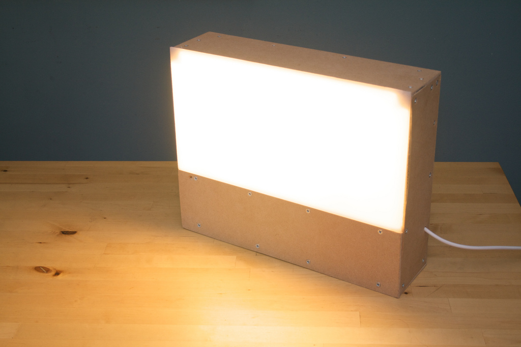
This design was inspired by Alex Campagna’s DIY Spiderlight Strobe, the key differences being that this uses an all-wood design, with no need for a metal junction box, and that it is an entirely enclosed box so it can be used as a free-standing lamp, or as a lightbox.
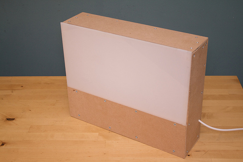
Essentially, this lamp consists of 4 × 20W energy saver bulbs (about 100W each equivalent in tungsten bulbs), wired in parallel and enclosed in a refectlive box with optional diffusion screen.
Materials
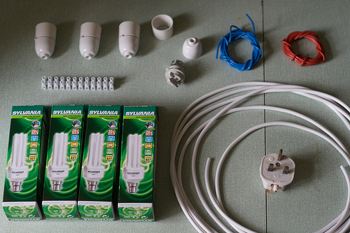
Electricals
- 4 × CFL lightbulbs (the brightest you can find, I used Sylvania 20W bulbs, natural daylight bulbs would be better)
- 4 × lamp holders (available from any decent electrical supplies merchant, bayonet or screw fitting to match your bulbs)
- 5m dual core cable
- Some extra dual core cable and insulted wires to connect the bulbs
- Plug
- Cable clamp
- Terminal strip
Case
- 1/8″ MDF or wood (I bought a piece about 1m square)
- 3/4″ Wood beading (I used about 3m)
- Translucent acrylic plastic
- Aluminium foil
- PVA glue
- Countersunk screws
Tools
- Wood saw
- Drill
- Wood drill bits
- Adjustable hole saw drill bit or spade bit
- Countersink drill bit
- Screwdriver
- Hack saw (useful for cutting beading)
Steps
Please note, I’ve provided these instructions to help others make their own lamps, but I am not a professional, trained or certified electrician. This project is powered by mains electricity, which can kill you. I make no claims as to the safety of this project, so proceed at your own risk. If you are an electrician, or know about these things, and can help improve the instructions, please let me know.
1. Wire up the bulbs in parallel
Parallel is the key word here. Wired this way, all the bulbs draw full power from the supply and operate at full brightness. For the purposes of safety and component specification, this means that your power draw and current will be a factor of the number of bulbs used, in my case, 80 Watts (= 4 × 20W) and 1/3 Amp (= 4 × 20W ÷ 240V).
Don’t do any of this wiring with the mains cable plugged in. I didn’t even wire up the mains plug until much later.
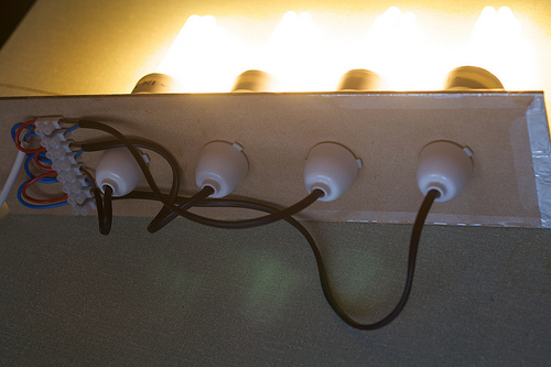
Connect your mains cable to the first two blocks on one side of the terminal strip, (live to the left, neutral to the right), then daisy chain each wire out to alternate blocks, until you have wired up enough for all your bulbs (4 pairs of blocks in my case, 3 done so far in the photo).
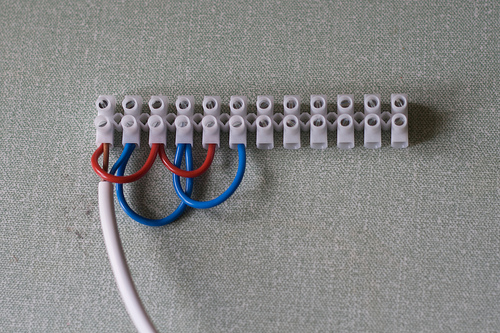
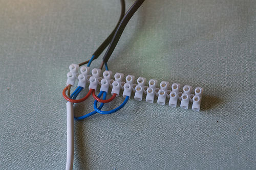
Then connect each lamp holder to the other side of each pair of blocks (the black cables in the photo), allowing a slightly longer cable for each lamp as it will be placed further away from the terminal strip when fitted.
When you have all four lamps connected, and you’ve wired up the mains plug, you’re ready to fit the electrical assembly into its holding plate. If you want to test it at this point, know the risks. You are playing with mains electricity, and if you touch any part of the assembly before fitting an insulated case, you could easily electrocute yourself. Make sure to unplug it before going any further.
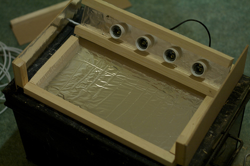
2. Fit the bulbs into the holding plate
The lamp holders have two plastic sleeves designed to hold a lamp shade. However, we can make use of them to fit the bulbs into a plate which will then be mounted into a box. The terminal strip can also be mounted onto this plate.
Decide how big your box will be. Mine was about 16″ wide, 13″ long (along the length of the bulbs) and 4″ high. This gave me enough room to fit four bulbs with adequate spacing, plus the terminal strip with space in front of the holding plate for the bulbs themselves, and space behind (about 4″) for the wiring.
Cut your holding plate from the MDF. It will need to be thin enough to allow the sleeves of the lamp holders to screw down securely. (I used 1/8″ MDF).
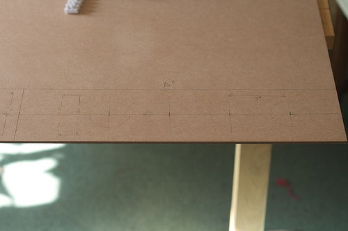
Mark out on the MDF where your lamp holders and terminal strip will go. I allowed a 3″ space between the central points of each bulb, giving about 1 1/2” space between each bulb when fitted.
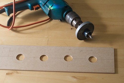
Drill holes for the lamp holders using a hole saw (as pictured above) or spade bit. Better to create holes a little on the small side and then open them up with sand paper than drill them too large. You want a snug fit for the lamp holders.
Cover the front of the panel with aluminium foil, glued on with PVA adhesive. Its easiest to spread this on very thinly with a piece of card or plastic. Cut out the foil where it covers the holes you’ve just drilled.
Push the lamp holders through the holes and secure with the sleeves.
Screw the terminal block into place on one side of the panel.
Secure the mains cable to the panel with a cable clamp to avoid putting strain on the connections to the terminal block when in use (not pictured above).
If you test again here, remember, it’s still very dangerous!
3. Cut the case panels
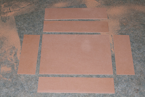
You will need to cut 6 more pieces of MDF or wood for the case, plus 1 piece of clear or translucent plastic:
- 1 base (16″ × 13″)
- 2 sides (4″ × 12 3/4″)
- 1 front (4 1/4″ × 16″)
- 1 back (4 1/4″ × 16″)
- 1 partial wooden top cover (4 1/2″ × 16 1/4″)
- 1 partial plastic top cover (8 1/2″ × 16 1/4″)
These measurements assume you’re using 1/8″ thick material to make a box 16″ × 13″ × 4″. You will have to adjust these depending on how you want your pieces to fit together, i.e. whether you want the top to overlap the sides, or the front to overlap the top, etc.
Glue aluminium foil to the inside faces of each piece, except the back, and top partial wooden panel.
4. Cut and fit the wooden beading
Because MDF is composed of compressed dust, you cannot hold it together with screws. The screw head will hold a sheet of MDF securely, but only when the thread is screwed into something that will grip it. I used wooden beading, though I believe you can also buy plastic brackets made for this purpose.
Every panel needs to be attached to its neighbours by screwing the beading to one panel, then screwing the second panel onto the beading. You may be surprised by how long this step takes — each hole has to be drilled twice, once for the screw, then again to countersink the screw head. Countersinking makes for a cleaner finish, and you can slide the box around on delicate surfaces without scratching them.
You may also be surprised by how much beading you need — I used about 3m in the end.
I’m not going to detail the beading for every panel, but a few of my steps are shown below.
Top and bottom of the internal holding plate
Bottom panel
Bottom panel, side panels and holding plate
Side panel, with hole drilled for power cable
Before you attach the side panels, remember to drill a hole for the power cord and feed this through.
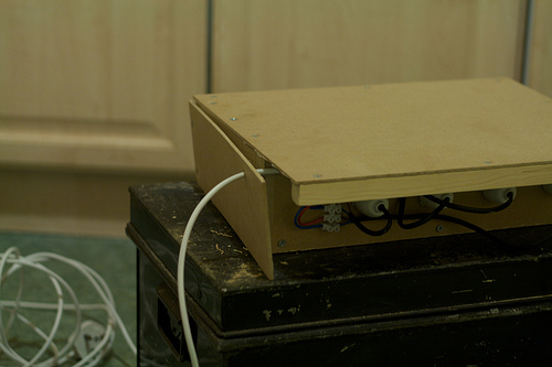
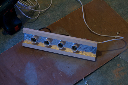
This final picture shows all the panels attached bar the top ones:
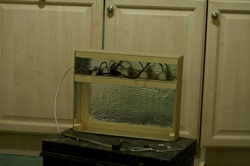
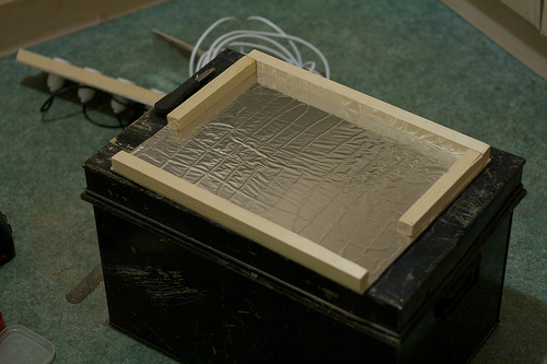
5. Fit the plastic screen
I had a piece of translucent plastic cut to size at a plastic merchant. Because I’m not yet sure I want this on all the time, and want to be able to access the bulbs inside, this isn’t attached permanently. It pretty much just stays on in most orientations, or I just use clear sticky tape when I want to fix it more securely.
Application
So far, I’ve used this for side lighting, rather than any experimental under lighting or as a lightbox.
The bulbs I’m using are not daylight bulbs. They have a colour temperature of about 2700-3000K. You need to adjust your white balance accordingly. I find that the tungsten setting in camera works pretty well.
As I don’t have a light tent, I’m using large sheets of plastic and card (from an art supplies store) to provide a clean backdrop and reflect the light from the top and opposite side.
The photos below show the box in use in a number of different setups, with the finished result and the setup together.
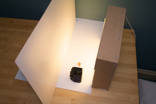
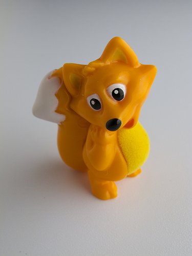
Macro
I turned the lamp upside down and pushed the reflector up close for this macro shot. I used the G11 to take the final shot pretty much from the position shown in the setup shot.
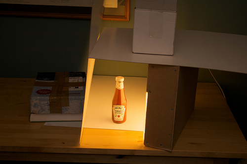
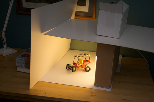
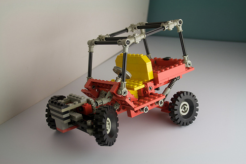
Mid-size product shot
Though the lighting in this shot is pretty good, you can see the limitations of the setup clearly here:
- It requires an elaborate arrangement of reflectors and a balancing act of books and boxes to get enough light onto all sides of the model. I really need another lamp.
- Even with these large sheets, I still couldn’t get a clean, uninterrupted background. I really need a light tent and infinity wall.
- The colour temperature of the bulbs is quite skewed. The setup shot was lit by my camera flash (bounced off the ceiling), and the white balance was corrected for this. You can see that the light from the lightbox is quite yellow by comparison. The final shot was WB corrected for the lightbox, which clears it up, but I’d still like to get better white balance from the light source.
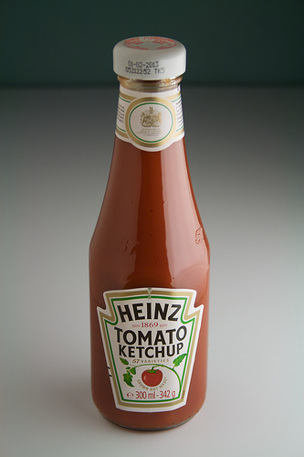
Model with specular highlights
I’m really pleased with this initial test. Although it’s not the most challenging of subjects, this glass bottle could cause problems for lots of lighting setups. The final shot has a pretty good mix of clean specular highlights from the lamp and from the reflector, with subtle diffuse highlights and shadows. Not bad for a 30 second setup.