RGB Projection Light
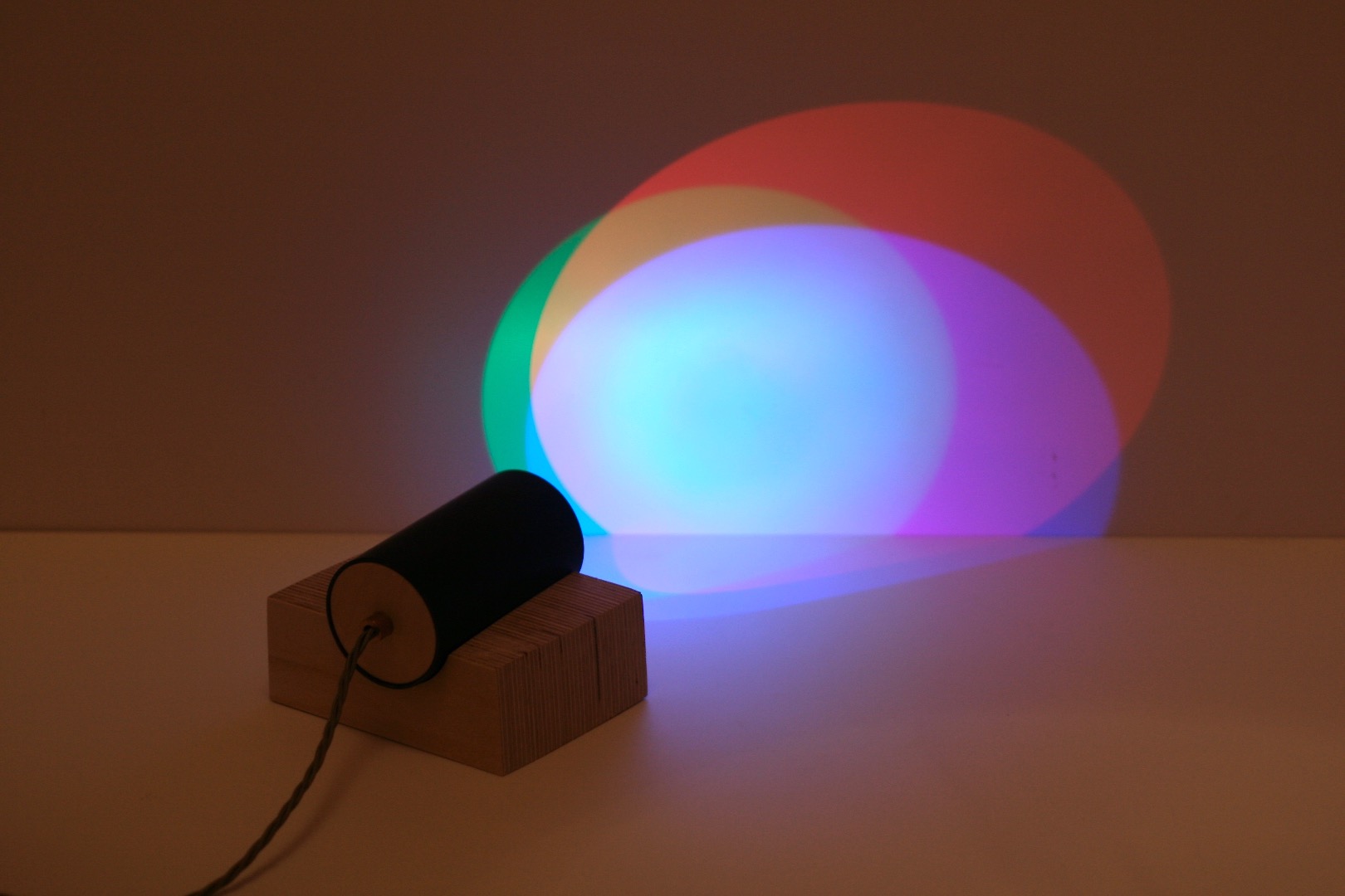
This LED lamp is a simple lighting project that reuses a three colour LED light and mounts it in a tube to create a colourful projection light that looks great when pointed against a wall.
Following these principles, you could take the project in many directions. For me it was an opportunity to try turning something functional but graceless into something simple and elegant, and to make it to a high standard by reusing existing materials that are high quality but also cheap/free.
You can also find this project on Instructables with complete photos.
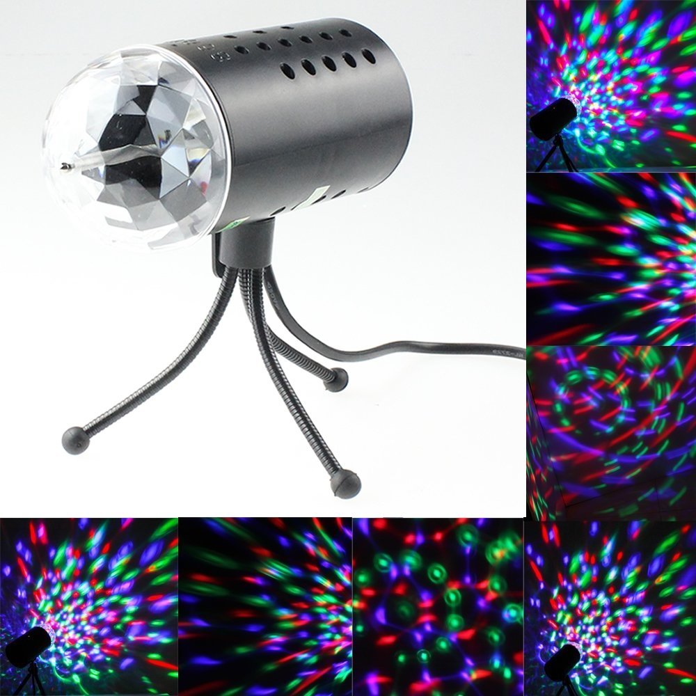
We had bought a cheap LED light from Amazon, designed to be used as a disco light for house parties. It has three LEDs (Red, Green and Blue) spaced apart on a circuit board. The board is mounted inside a black tube, and there’s a motor with a spindle running through the middle of the tube that turns a faceted clear plastic dome, through which the lights shine. The result is a shifting pattern of red, green and blue light (and mixtures thereof) on the wall. It runs off the mains, and has some kind of built-in transformer, but the design and build quality is kind of shonky, and the geared motor makes too much noise.
So we took it apart, and started playing around with the lights themselves. It turns out that if you mount just the lights inside a tube, and shine that against a wall, you get a lovely, simple pattern of overlapping coloured segments. So it’s a very colourful light, but the overall effect on the space is neutral.
I have basic power tools at home, but no fancy bandsaws or lathes, and I wanted to reuse existing high-quality materials, instead of going out and buying expensive, parts or new materials.
Step 1: Materials
This is what I used, but other than an LED light (a circuit board with three LEDs spaced apart), everything here could be swapped out for whatever you have available.
- Some scrap Plywood – it should be high quality, ‘BB’ grade furniture ply. I used 18mm birch ply. It doesn’t need to be that thick, but if you want to get the nice striped effect, you do need to use this high quality ply. Offcuts are fine.
- Some black PVC drainpipe, easy to find in skips
- LED light. Mine was this one from Amazon
- Some nice lamp flex, and optionally, some brass light cord fittings. You can get these easily on eBay. You can really have some fun choosing different kinds of flex.
- Wood glue, and I also used a hot glue gun for one part of the assembly.
- 2 x M4 bolts and 6 x M4 nuts
Step 2: Tools
- Hand saw (a rigid mitre saw works best) and mitre box – or some other means of making straight, perpendicular cuts. Clearly a table saw or band saw would be useful here.
- Drill. A pillar drill would be really useful for this project, but I don’t have one.
- Hole saw – this is the key tool. It needs to be the same size as your tube. In the UK, drainpipe is a standard 68mm diameter.
- Power sander – I did most of this with a random orbit sander, but it died halfway through (it was a Bosch sander – do not buy one of these, they are rubbish). A belt sander or bench-mounted sander would work much better.
- Sand paper (all grades from rough (60/80 grit) to smooth (super-fine wet-and-dry, e.g. 1200-grit)
- Soldering iron, solder and insulating tape or heat shrink insulation
Step 3: Cut the plywood for the base
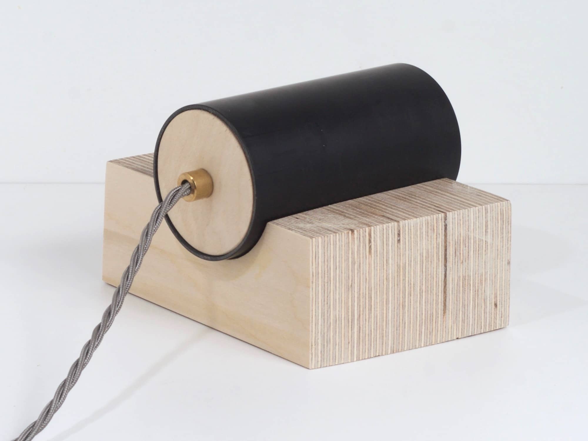
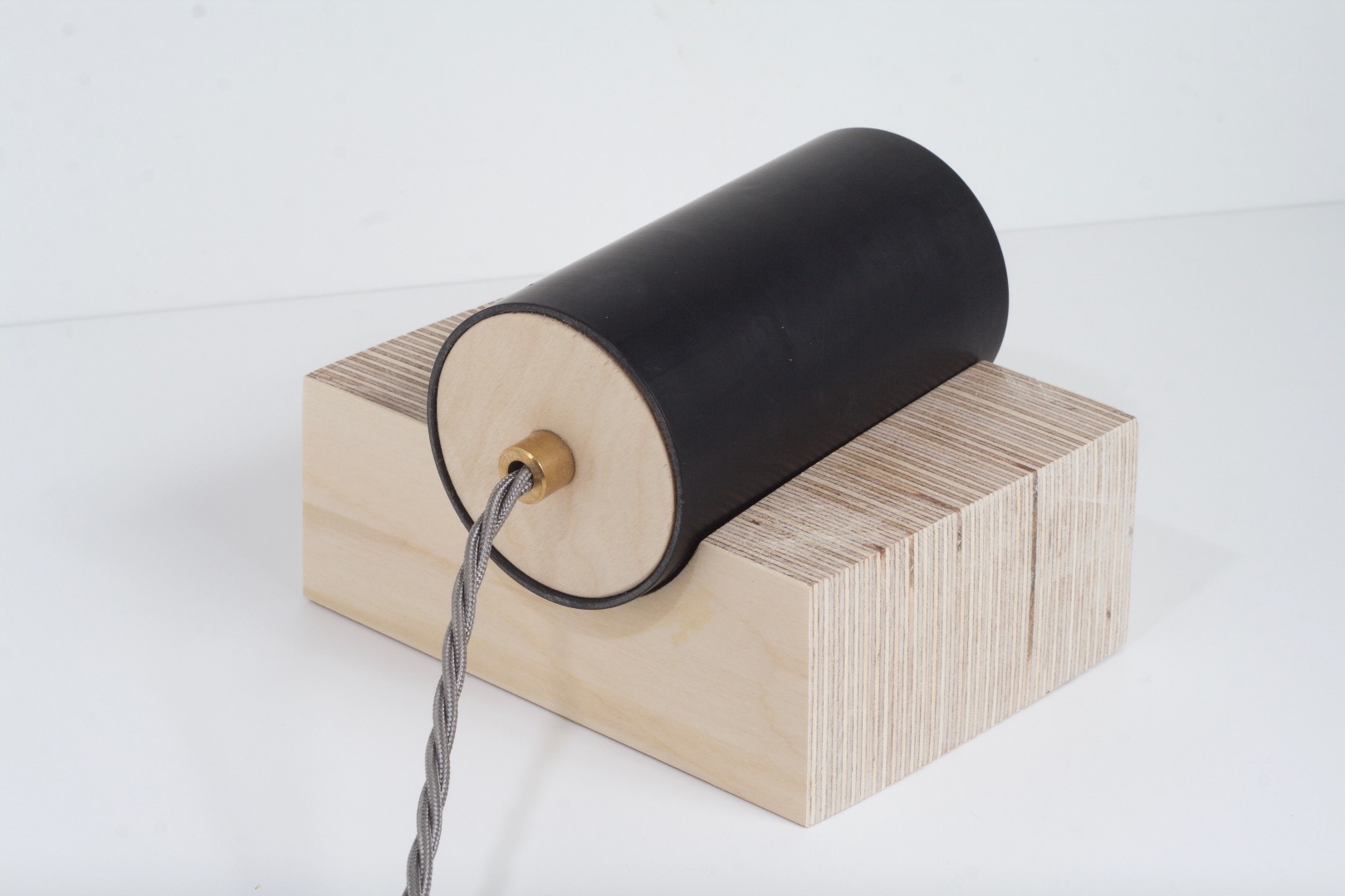
The basic design is a tube that rests horizontally in a wooden cradle, so the light can be projected at a wall.
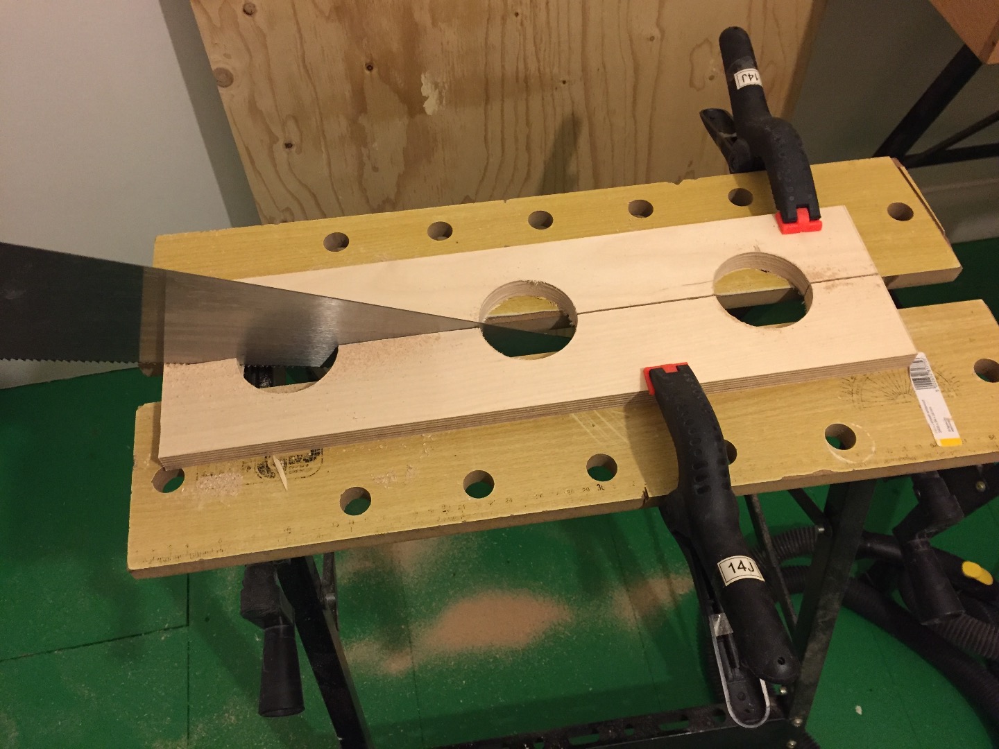
The base is made from several layers of plywood that are glued together. I used 6 layers of 18mm ply, which gave me a base about 11cm long. The base has a semicircular groove cut through the middle, to support the tube. That groove is made by cutting a disc out of each piece of ply, then slicing each piece of ply in half, giving you two pieces, each with a semi-circular cutout. Do that several times (I cut out 3 discs, giving me 6 pieces) and you have the layers you can glue together to form your base.
The key here is to use a hole saw with the same diameter as your tube. Most hole saws around this size in the UK are 70mm, but I managed to find a 68mm saw at Machinemart. With a kerf of about 2mm (about the same as the thickness of the PVC pipe) that gave me a groove of the right size in the base, and also a series of discs that could fit inside the tube to hold the circuit board and form the back plate.
You don’t need to be super-accurate when you cut the holes, because you can trim off all the uneven edges after gluing the ply sheets together. However, one thing that would help here is to try to drill perfectly vertical holes. A pillar drill makes this easy, maybe some kind of jig could help you do this with a hand drill. Either way, I paid the price later for my slightly off-axis holes.
Save the discs. You’ll need one or two of these to make the end plate of the lamp tube.
Step 4: Glue up and trim the base to size
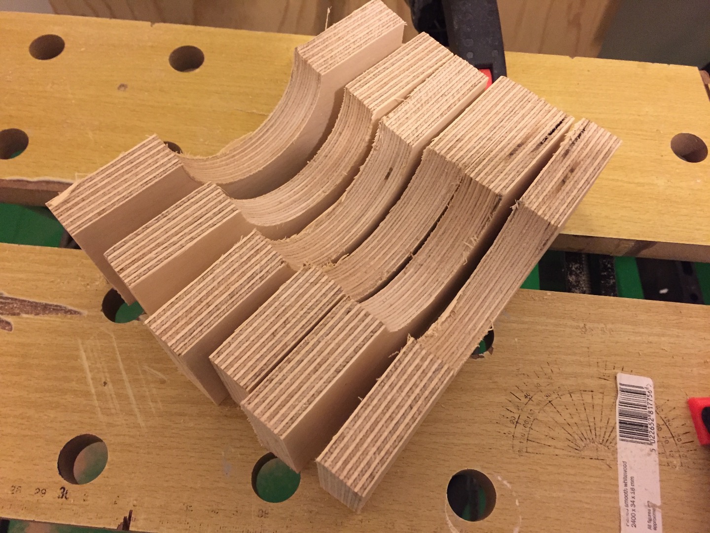
At this stage, you should have 6 or so sheets of plywood, each with a semicircular hole. Glue these up and clamp them overnight.
They will likely be roughly cut at this stage, which is OK, just try to make sure the semi-circular holes all align well. Slop here results in lots of sanding later on. I was not careful enough here to line up all the sheets so the groove was perfectly perpendicular to the base, and I had to adjust my design later on to deal with this error.
Once it’s dry, the base is ready to trim to size, and sand to a nice finish.
Use a mitre box (or draw a straight line) and trim off each side to a flat face. I had planned to make a rectangular base, with the groove running perfectly up the middle, but as my groove turned out to be slightly off-angle, I decided to embrace it, and cut the base into a parallelogram shape.
Use a sander (a belt sander is best) to smooth each face, moving from 80 to 180 grit on the sander, and then finishing with 1000 grit by hand.
I sanded the groove by wrapping sandpaper round a piece of drainpipe and doing it by hand. This took a long time. The more precise your cuts, the less need for sanding.
As there was some unevenness I couldn’t sand away, I had to use some wood filler here too.
Step 5: Make the lamp tube
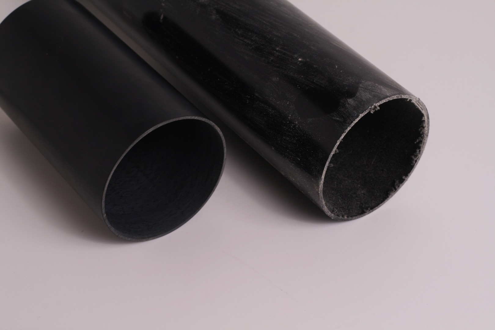
Cut a length of your drainpipe. It needs to be long enough to hold your LED circuit board, plus a mounting plate to hold it in place, plus a back plate to give a nice finish. I made my tube slightly longer than the base, so it protrudes about 1cm over each side.
Use sandpaper to clean up the sawn ends, and then wet-and-dry to take the gloss finish off the surface of the PVC. The key here is to use the finest grade (1000 grit or more) sandpaper you can, and to do it under the tap – wet, not dry. That gives you a nice mat finish, without scratches. You might be pleasantly surprised at how nicely the drainpipe turns out.
Step 6: Mount the LED circuit board
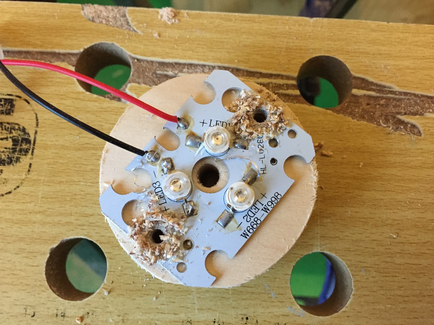
Fortunately, the circuit board I used was a pretty good fit for the tube, with only a little needing to be taken off the corners with a hacksaw.
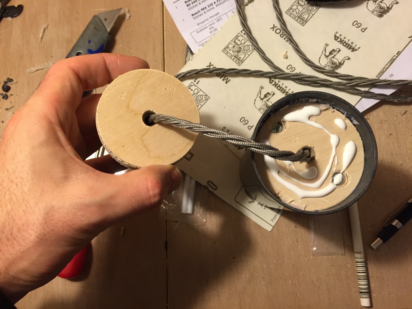
Using existing mounting holes on the board as a guide, drill two 4mm holes into one of the plywood discs, then flip the disc over and made large countersinks on the reverse to accommodate the head of an M4 bolt.
Put the bolts through from the back of the disc, followed by a nut tightened down to hold it in place. Then another nut a couple of centimetres up the bolt to space the board away from the disc. Then the board itself, then another nut to hold it in place.
Step 7: Wire up the LED board to the power cord
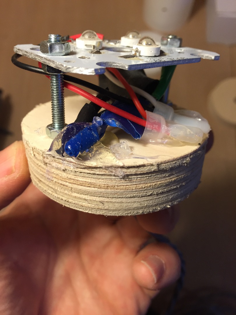
The LED light comes with an ugly power cord that you probably don’t want to use, so trim this off, just before it is attached to the transformer, keeping a note of which wire goes where.
Your wooden disc should have a hole in the middle where the arbor for the hole saw cut through. Widen this if necessary, then thread through the cable you want to use. Solder this up to the wire on the board. Cover the exposed ends with insulation tape or heat shrink insulation.
Now would be a good time to test the light to see if it works.
It it’s all in order, you can use a hot glue gun to fix any loose components or wires to your plywood disc.
Step 8: Make the back plate
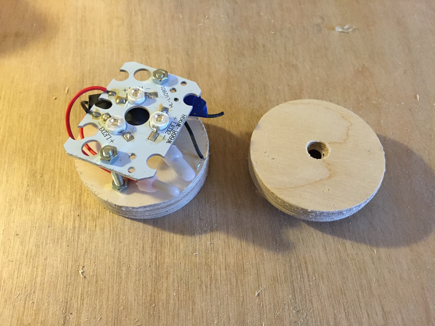
I used a second disc to make a separate back plate. You could probably get away with just one, but this gives you more flexibility in where you position the LEDs in the tube, and adds some heft to the light.
Place the disc with the LED board attached into the tube, switch it on, and slide it up and down the tube until you’re happy with the shape of the light it produces.
Use a hot glue gun to fix this in place. You can be messy here, as it’s all covered up by the back plate.
In my case, this was with the mounting disc about 18mm from the back of the tube, so I could just glue my (18mm thick) back plate right onto the mounting plate.
I also added a small brass cord grip into the back plate to hold the cord securely, and finish the hole nicely.
Step 9: Finished
You may want to varnish or paint the wooden parts at this point, but basically, you’re done.
I’d love to see any variations on this idea. So please do share anything you’ve made along these lines.
(These final images show a version before I’d done the final sanding, so they’re a bit scratchier than the final product)