Vasarely desktop wallpaper generator
After attempting to recreate a Vasarely painting, and realising that the original was not quite as simple as it appeared at first, I tried instead to use the idea of a tessellated geometric pattern that appear to be a field of 3D objects lit with shifting and unnatural colours to make some nice desktop wallpapers instead. This allowed me to play with something else I wanted to get a handle on – onscreen GUI controllers, in this case provided by the ControlP5 library. I’ve tried using them before, and found the library tricky to get my head around, but it feels a bit clearer now.
Sketch: vasarely_traces_desktop_4.pde
Note: perlin noise update After I wrote up these docs, I figured out how to add some ramdom noise to the pattern created, so there are now noise sliders and functions in each of the colour calculations that are not referred to anywhere in these notes until you get to the update below.
This sketch uses the same nested object approach as the previous one but in some ways is much simpler, as the RGB values for each face are all calculated the same way.
The display() function for each cube looks like this:
void display(float centerX, float centerY, float cubeHeight,
  int cubeLeftColorR, int cubeLeftColorG, int cubeLeftColorB, // left face colours
  int cubeTopColorR, int cubeTopColorG, int cubeTopColorB, // top face colours
  int cubeBottomColorR, int cubeBottomColorG, int cubeBottomColorB // bottom face colours
  ) {
    cubeLeft.display(centerX, centerY, cubeHeight, cubeLeftColorR, cubeLeftColorG, cubeLeftColorB);
    cubeTop.display(centerX, centerY, cubeHeight, cubeTopColorR, cubeTopColorG, cubeTopColorB);
    cubeBottom.display(centerX, centerY, cubeHeight, cubeBottomColorR, cubeBottomColorG, cubeBottomColorB);
}
So after some positioning variables (float centerX, float centerY, float cubeHeight), it expects to get a series of RGB values for each face: 9 integers in total. It then passes those values onto the display() function for each face object.
And the calculation for each of these RGB values follows the same format each time. Here’s the calculation for the red value of the left face of a cube:
int(
  LeftFaceRed
  *
  // bulge factor
  (generateSeed(centerX, centerY) +
  ((1 - generateSeed(centerX, centerY)) * (1-LeftFaceCenterBulge)))
  *
  // gradient factor
  ((currentRow/rows) +
  ((1-(currentRow/rows)) * (1-LeftFaceTopDownGradient)))
)
It just multiplies 3 factors together:
LeftFaceRedis a variable from 1-255 that it gets from one of the slider controls (more on that below)- the bulge factor is a value of 0-1, as is the gradient factor. Each of these is in turn calculated from the position of the current cube (how far it is from the centre, or how far down the screen it is), multiplied by another factor also controlled by a slider (
LeftFaceCenterBulgeorLeftFaceTopDownGradientrespectively). So these sliders control how much each of those factors affects the colour, and can bring any value ofLeftFaceReddown to near zero
The whole lot is then converted to an integer, which is probably uneccessary.
Why the compicated maths? It’s because I want to take a value in the range 0-1, and adjust it, not to bring the high end of the range down, but to bring the low end of the range up. If I don’t want the colour to be affected at all by the position of the cube, I want the bulge and gradient factors to be equal to 1.
For example, take a cube in the middle row – say, row 5 of 10 total rows. In this case, I set the slider for LeftFaceTopDownGradient to be at its lowest value (0), so:
currentRow/rows = 0.5
1-(currentRow/rows) = 0.5
1-LeftFaceTopDownGradient = 1
(1-(currentRow/rows)) * (1-LeftFaceTopDownGradient) = 0.5
((currentRow/rows) + ((1-(currentRow/rows)) * (1-LeftFaceTopDownGradient))) = 1
So the “gradient factor” is 1, and therefore has no effect. Let’s set LeftFaceTopDownGradient to be 0.5 instead:
currentRow/rows = 0.5
1-(currentRow/rows) = 0.5
1-LeftFaceTopDownGradient = 0.5
(1-(currentRow/rows)) * (1-LeftFaceTopDownGradient) = 0.25
((currentRow/rows) + ((1-(currentRow/rows)) * (1-LeftFaceTopDownGradient))) = 0.75
Here, the “gradient factor” is 0.75, so a colour value for a cube in the middle row is 75% of the maximum set. So the effect of the cube’s position on the canvas is only partially applied. Now let’s set LeftFaceTopDownGradient to be 1:
currentRow/rows = 0.5
1-(currentRow/rows) = 0.5
1-LeftFaceTopDownGradient = 0
(1-(currentRow/rows)) * (1-LeftFaceTopDownGradient) = 0
((currentRow/rows) + ((1-(currentRow/rows)) * (1-LeftFaceTopDownGradient))) = 0.5
Here, the “gradient factor” is 0.5, so a colour value for a cube in the middle row is 50% of the maximum set. And a cube in the last row would have a colour value of 0% of the maximum. In these cases, the gradient effect is fully applied.
Using ControlP5 to make a GUI
I had some difficulty getting this to work, so here are my notes on this to remember.
1. Import library and declare all variables
I initially forgot I had to set up these variables so none of my sliders worked.
import controlP5.*;
ControlP5 cp5; // Declare ControlP5 object  - mine is called cp5
float LeftFaceRed;
float LeftFaceGreen;
float LeftFaceBlue;
float LeftFaceCenterBulge;
float LeftFaceTopDownGradient;

float TopFaceRed;
float TopFaceGreen;
float TopFaceBlue;
float TopFaceCenterBulge;
float TopFaceTopDownGradient;

float BottomFaceRed;
float BottomFaceGreen;
float BottomFaceBlue;
float BottomFaceCenterBulge;
float BottomFaceTopDownGradient;
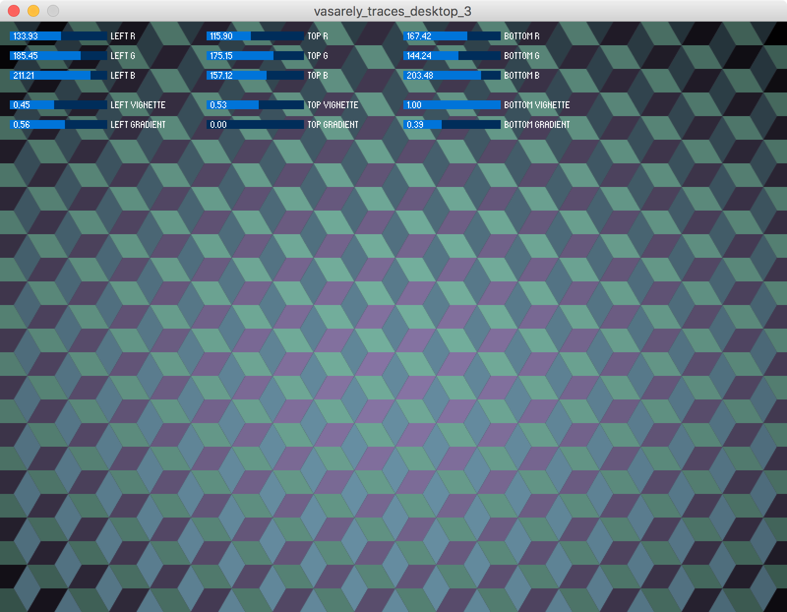
2. Setup GUI elements
These sliders are all setup in setup(). First, you initialise the ControlP5 object, which contains all of the GUI elements, then you add elements to the object (addSlider()) and set their properties (setRange(), setPosition(), etc.) using methods contained within that library object.
cp5 = new ControlP5(this);

cp5.addSlider("LeftFaceRed").setRange(0,255).setPosition(10, 10).setCaptionLabel("Left R");
cp5.addSlider("LeftFaceGreen").setRange(0,255).setPosition(10, 30).setCaptionLabel("Left G");
cp5.addSlider("LeftFaceBlue").setRange(0,255).setPosition(10, 50).setCaptionLabel("Left B");
cp5.addSlider("LeftFaceCenterBulge").setRange(0,1).setPosition(10, 80).setCaptionLabel("Left Vignette");
cp5.addSlider("LeftFaceTopDownGradient").setRange(0,1).setPosition(10, 100).setCaptionLabel("Left Gradient");

// etc...
3. Grab the values from each GUI element
Assuming you have them setup, this bit is easy, and you can see these variables being referred to in the functions above (LeftFaceRed, LeftFaceCenterBulge, etc.).
PDF export
I’m using another library, processing.pdf, to allow the conavas to be captured as a PDF. Fortunately this does’t include the sliders, and creates a resolution-independent vector file (ie not just a screenshot), which can then be cropped and scaled ot suit any screen.
Other than the import statements, it just need 2 sections of code, one just after draw() starts:
if (record) {
  beginRecord(PDF, "frame-####.pdf");
}
And one function:
void keyPressed() {
  if (key == 'p' || key == 'P') {
    record = true;
  }
}
Other ways to control colours
Earlier versions of this sketch used other factors to control the colours of the cube faces, such as mouse position, and time elapsed, which can make for very responsive or trippy effects, repectively. To use time to shift a colour smoothly over each redraw, add this code at the end of the draw() function, and then use currentFrame (assuming you declared it as an integer up top) as the value for one of your colours:
if (currentFrame >= 255) {
  currentFrameIncrement = false;
} else {
  if (currentFrame <= 0) {
    currentFrameIncrement = true;
  }
}

if (currentFrameIncrement) {
  currentFrame++; // increment the timer
} else {
  currentFrame--;
}
currentFrameIncrement is a poorly named boolean I used to determine whether to run the values up or down. You can control the speed of animation by altering the frame rate of the sketch.
You can also use a random function to add some texture, but it would change with each screen refresh, which could be a nice visual effect, but not much use if you’re trying to control the colours to make a specific pattern.
Update: Using Perlin noise
Becuase Perlin noise is deterministic, you can use this to add some texture to the image, without it changing on every screen refresh. I just added this extra multiplier to each colour calculation:
*
(noise(i+3900) +
((1-noise(i+3900)) * (1-LeftFaceNoise)))
i is the count of the cube objects, so each cube has a different seed value, and I added arbitrary numbers (3900 above) for each of the nine colour values so that the noise() function samples from different points of the spectrum for each colour value. (Otherwise, you get clumps of similar brightness where every RGB value of each face of a cube is being altered by a noise effect from the same part of the noise space (the value of i at that time).)
Get the desktops
If you’d like to play around with this, you can just download the sketch from Github and run it yourself from Processing (which is free to use). Here are a few desktops I made, saved as PDFs, which you can crop and resize as you like.
Some more desktops after I added the noise function: