LM386 Amplifier
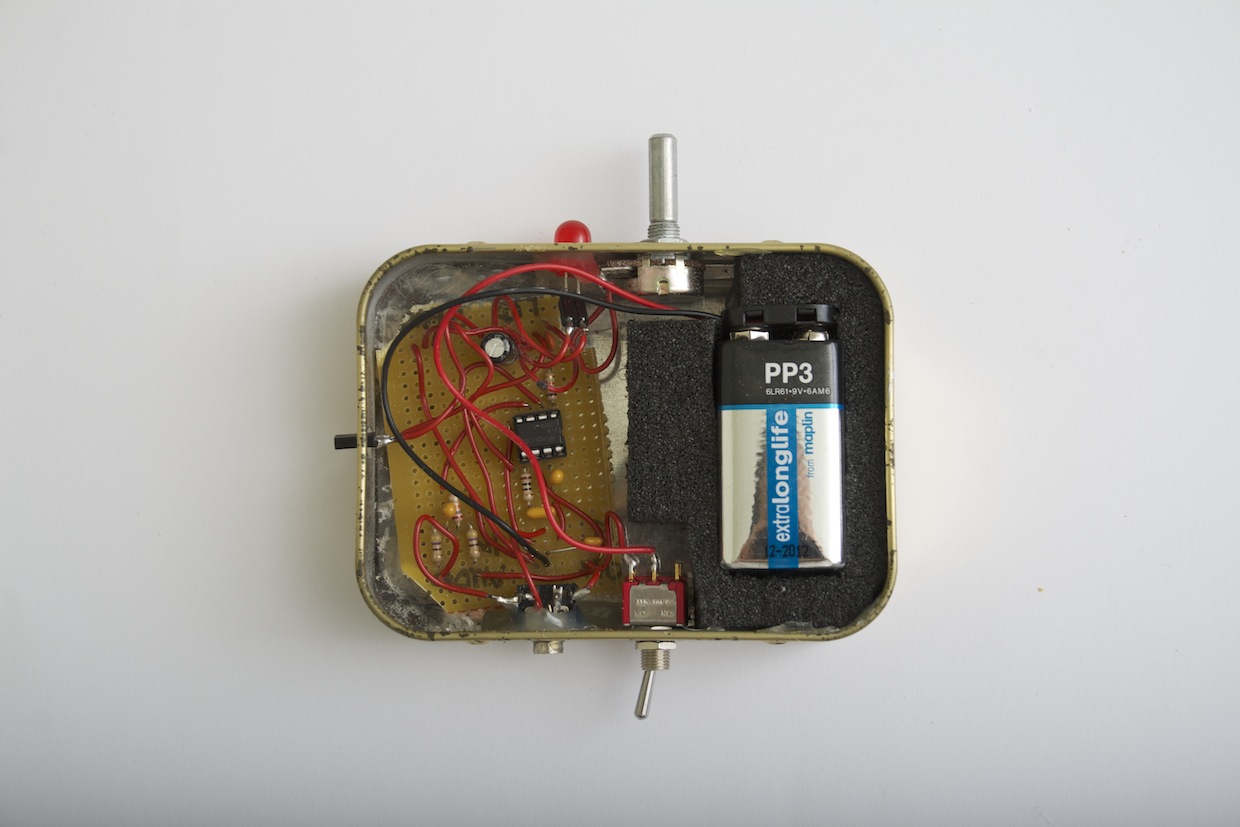
The LM386 chip is a simple and cheap amplifier chip that is used in countless audio amplifier projects. I used one to make my own 0.5W amplifier.
This is not a complete how-to guide, you can find plenty of those elsewhere. It’s just a write-up of some of the things I learned – and modifications I made – along the way.
Instructions
I largely followed the instructions on the Hack A Week site, with a few modifications.
I added a stereo-to-mono summing circuit to convert the stereo signal from my audio source down to a mono signal for the amp. More on these circuits:
http://www.rane.com/note109.html
http://www.psychicorigami.com/2013/04/30/a-small-monobox-speaker-lm386-amp-speaker-in-a-box/
I made a few modifications to deal with interference problems from my power supply, as per this write-up.
And I added a few extra parts, as detailed below.
Parts
As a result of these modifications, my final parts list ended up being quite different to the standard lists for these kinds of projects.
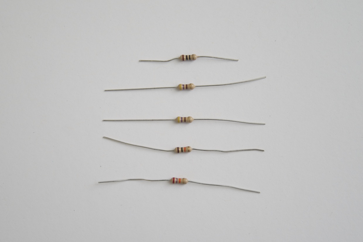
Resistors
From top to bottom:
- 1 x 10 Ohm resistor (pin 5 to ground)
- 2 x 470 Ohm resistor (for stereo summing circuit)
- 1 x 27K Ohm resistor (for stereo summing circuit)
- 1 x 10K Ohm resistor (for bass boost circuit)
Capacitors
From left to right:
- 1 x 0.047 uF non-polarised (decoupling capacitor, voltage high to ground)
- 1 x 0.47 uF non-polarised (pin 5 to ground, original circuit specifies 0.047 uF)
- 1 x 2.2 uF polarised (bypass capacitor, pin 7 to ground)
- 1 x 0.1 uF polarised (pin 3, signal in, high)
- 1 x 0.022 uF non-polarised (pin 1 to pin 5, bass boost circuit)
- 1 x 100uF polarised (pin 5, just before the speaker in the circuit, original circuit specifies 220uF)
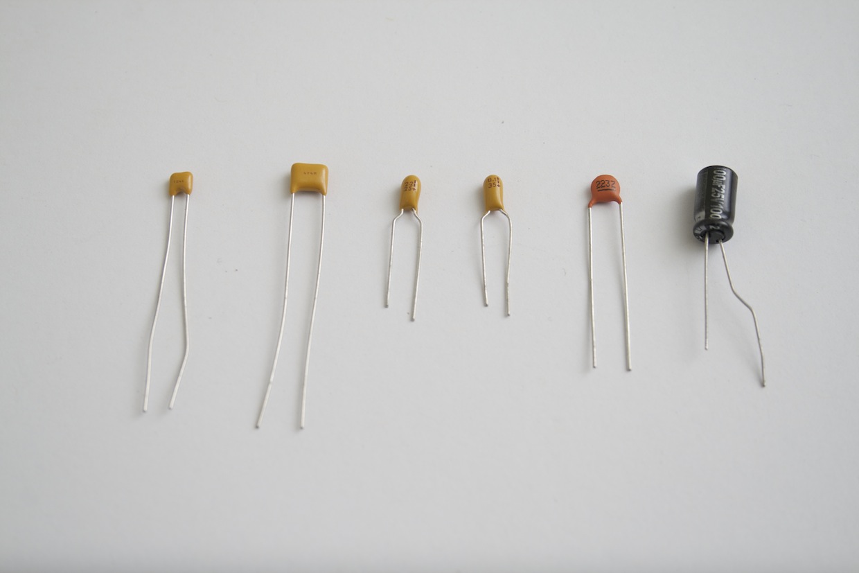
The instructions on Hack A Week call for almost entirely different values. I found that by swapping out different capacitors I could get better results.
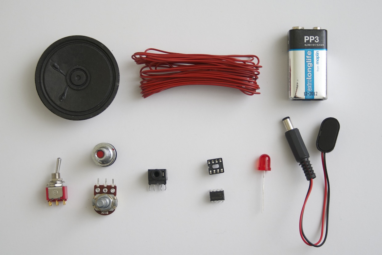
Other components
- LM386(N) chip
- 8-pin DIP socket
- 9V battery and connector, or 9V power supply
- 8Ohm 0.5W speaker
- Wire
- 10K potentiometer (I used linear, but a logarithmic potentiometer is probably better) and knob
- Switch
- 1 x power and 2 x mini-jack sockets (for audio in and audio out, assuming your speaker is wired separately)
- LED (optional, for a distortion indicator)
- Breakaway female headers (not shown, optional, to allow you to swap out some of the components)
Enclosure
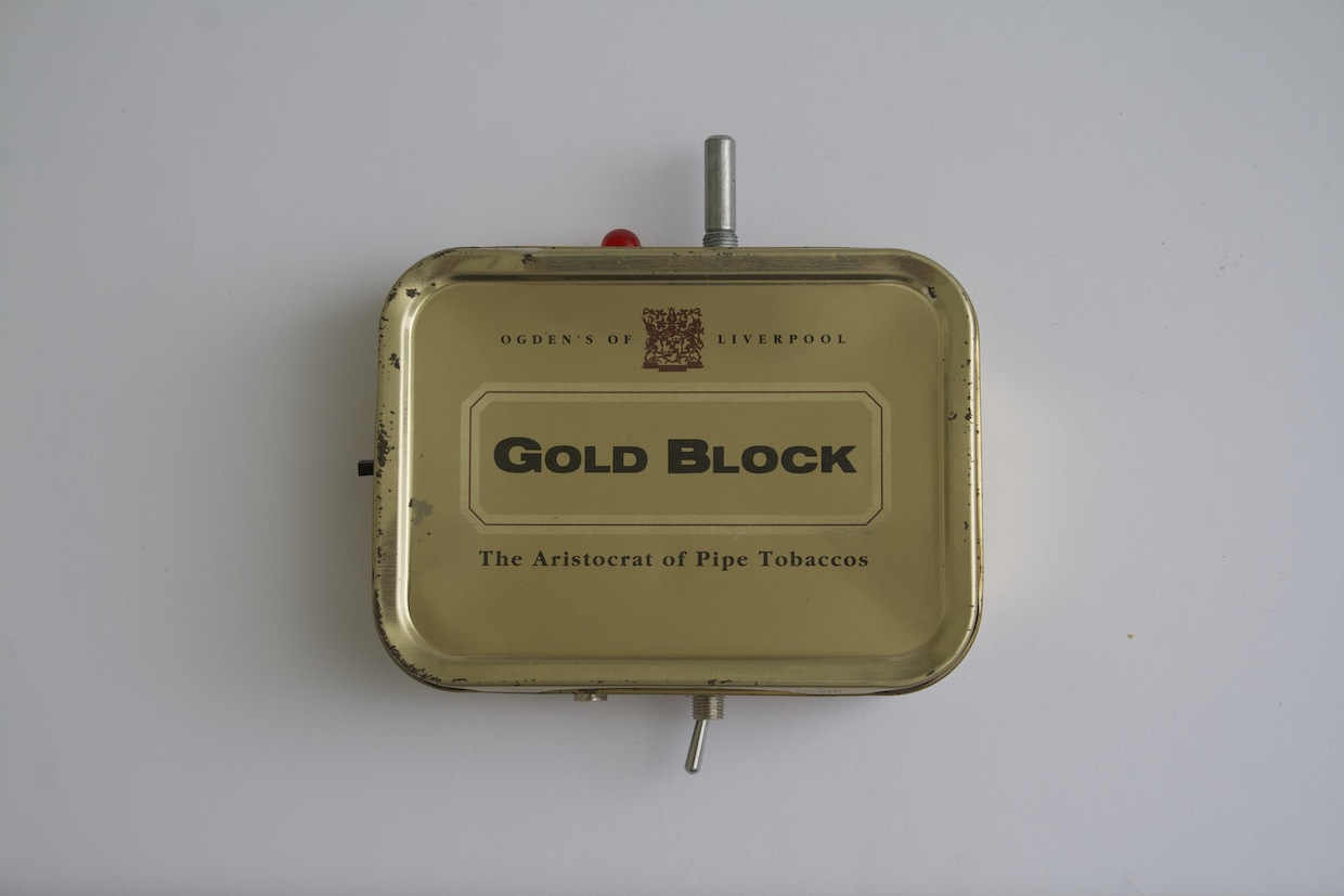
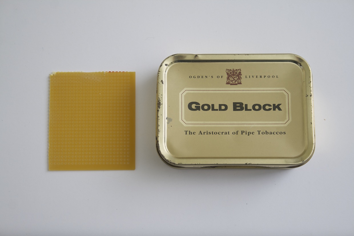
I used an old pipe tobacco tin, and some perfboard to mount the components for the final project.
Breadboard prototyping
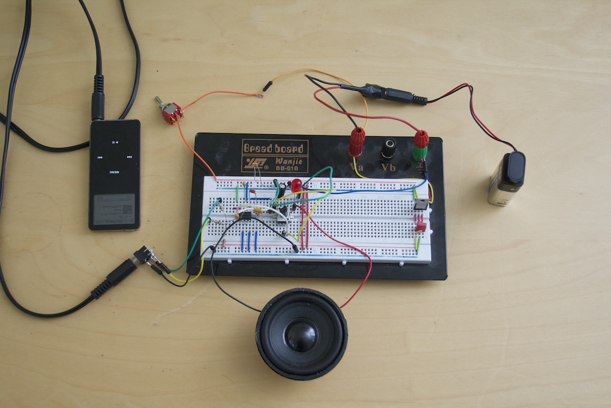
I built the circuit on a breadboard first, and this where I solved most of the problems.
Interference
90% of the time I spent building this circuit I was dealing with unwanted interference, either a hum when no audio input was plugged in, or distortion to the amplified signal.
Some research turned up a few mods designed to address this problem, and after lots of trial and error, I settled on:
- 1 x 0.047 uF non-polarised decoupling capacitor, between voltage high and ground, near the power in.
- 1 x 2.2 uF bypass capacitor, between pin 7 and ground.
I also found that a battery caused far fewer problems than an AC-DC adapter, and that a 9V supply performed better than 5V or less.
Pre-amp gain control
Most LM386 circuits allow you to adjust the gain of the incoming signal. I ditched this part, on the basis that I could do it more easily with the volume control on the audio device I’m plugging in.
Post-amp volume control and indicator
At the same time, I couldn’t resist adding a different unnecessary knob – and LED – to the enclosure, so I put in a potentiometer and LED wired in parallel between pin 5 and the speaker. The LED is completely redundant. It lights up when the signal reaches a certain point, which is also the point when it starts distorting, so you could argue that it’s a useful visual clipping indicator, so that’s what I’ll be doing.
Stereo summing
The circuit amplifies one signal only. To amplify a stereo signal you’d need 2 chips and 2 speakers. While you could wire up the audio input to just one of the left or right channels, for some recordings, this would result in a strange loss of signal.
So it’s tempting to just wire the left and right inputs together, but do that, and you could end up with some nasty things happening:
Here is the rule: Outputs are low impedance and must only be connected to high impedance inputs — never, never tie two outputs directly together — never. If you do, then each output tries to drive the very low impedance of the other, forcing both outputs into current-limit and possible damage. As a minimum, severe signal loss results.
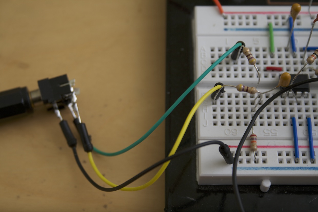
So I added a proper stereo summing circuit before pin 3.
Making the enclosure
My reason for making this circuit was largely so I’d have an excuse to make a box. I used an old tobacco tin, and cut a piece of perfboard to fit inside, leaving room for the 9V battery. I figured out where I wanted the external controls and sockets to go, and then marked on the board where I would put each part of the circuit.
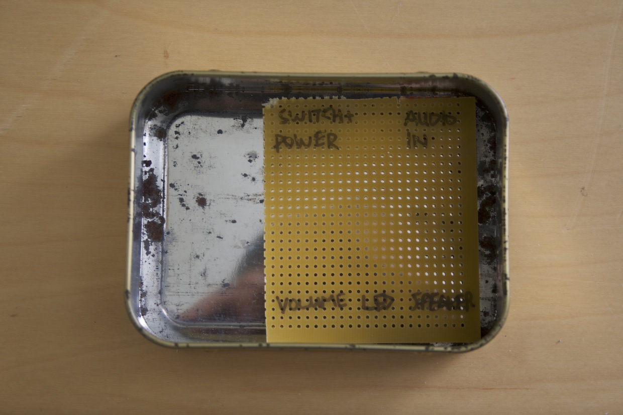
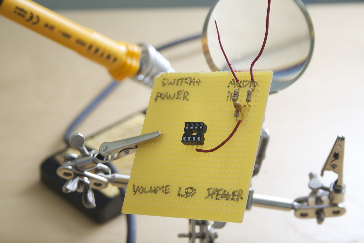
Starting with the DIP socket, I started to wire up all the components.
When I had all the board-mounted components soldered on and wired up, I turned my attention to the case.
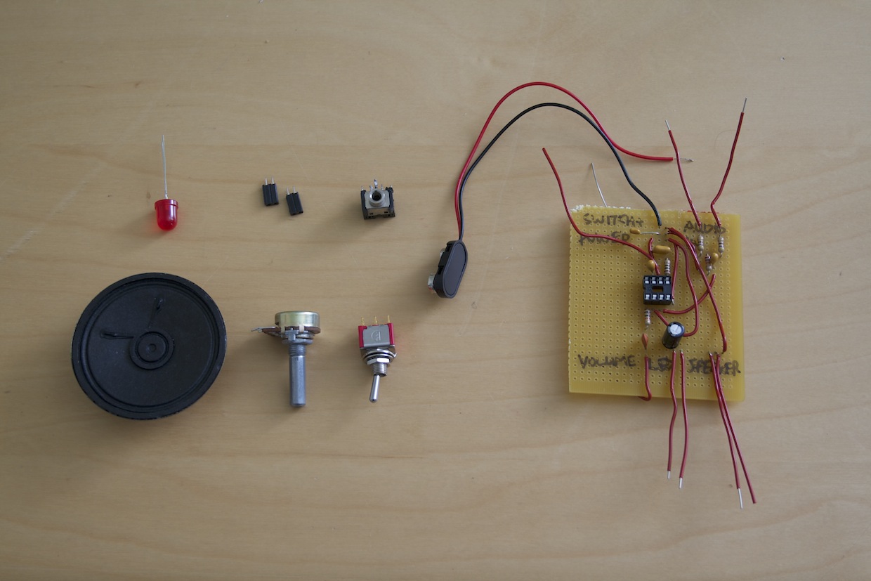
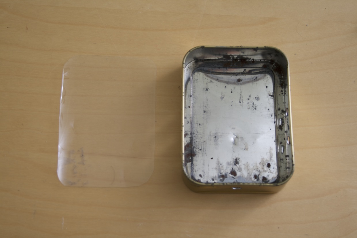
I drilled holes in the case for the power switch, audio in socket, speaker out socket, volume knob and LED. I lined the bottom of the case with a piece of plastic to avoid shorts.
Before fixing the positions of all the controls, and while I could still easily remove the circuit board, I wired everything up one more time to test the circuit.
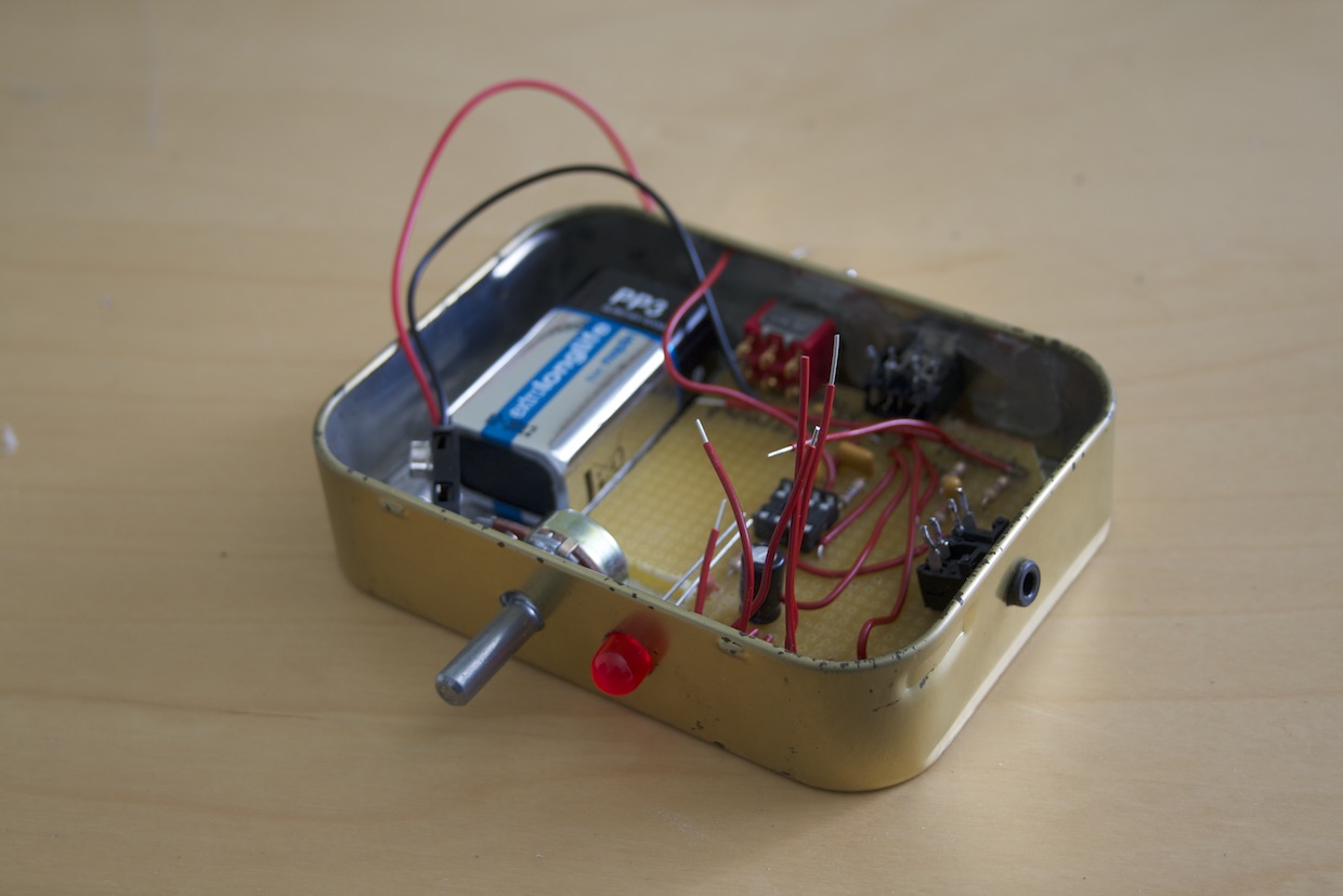
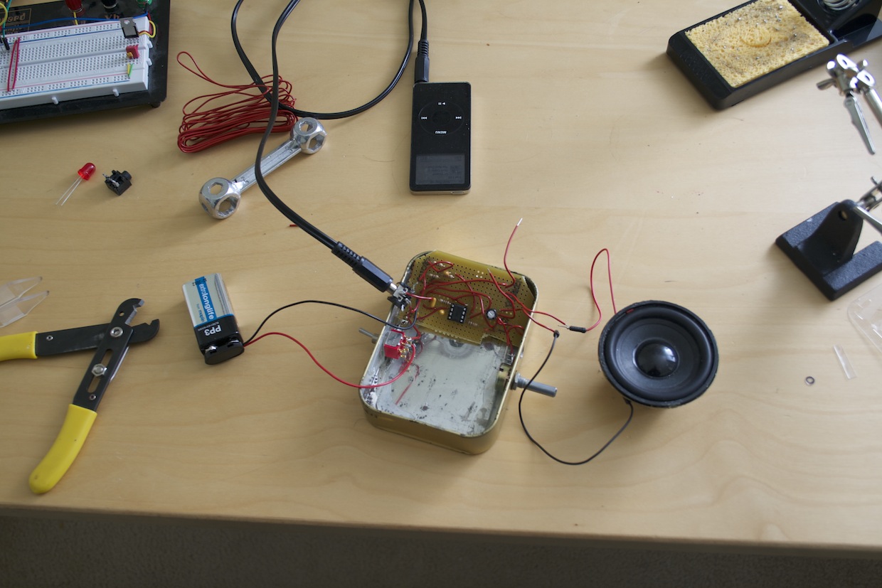
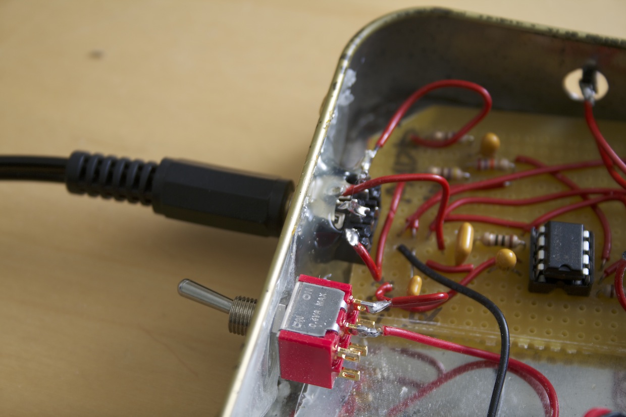
Some of the parts were proper panel-mount components with nuts and washers to secure them to the case. Others I’d stripped from old circuit boards and were designed to be PCB-mounted. These I had to mount to the case with hot glue. Clearly this is a less than ideal solution for a component that is put under strain every time you plug something in.
I’m ordering some panel-mount mini-jack sockets, so until these arrive, I left the audio output wires terminated with a female header, to which I can easily temporarily plug in wires from the speaker.
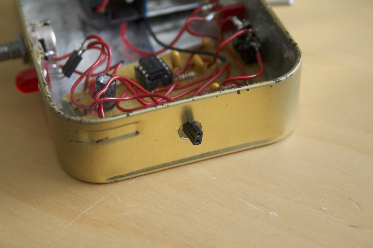
The LED is also mounted with hot glue. I also wired this up via a header so I could replace it if I burned it out.
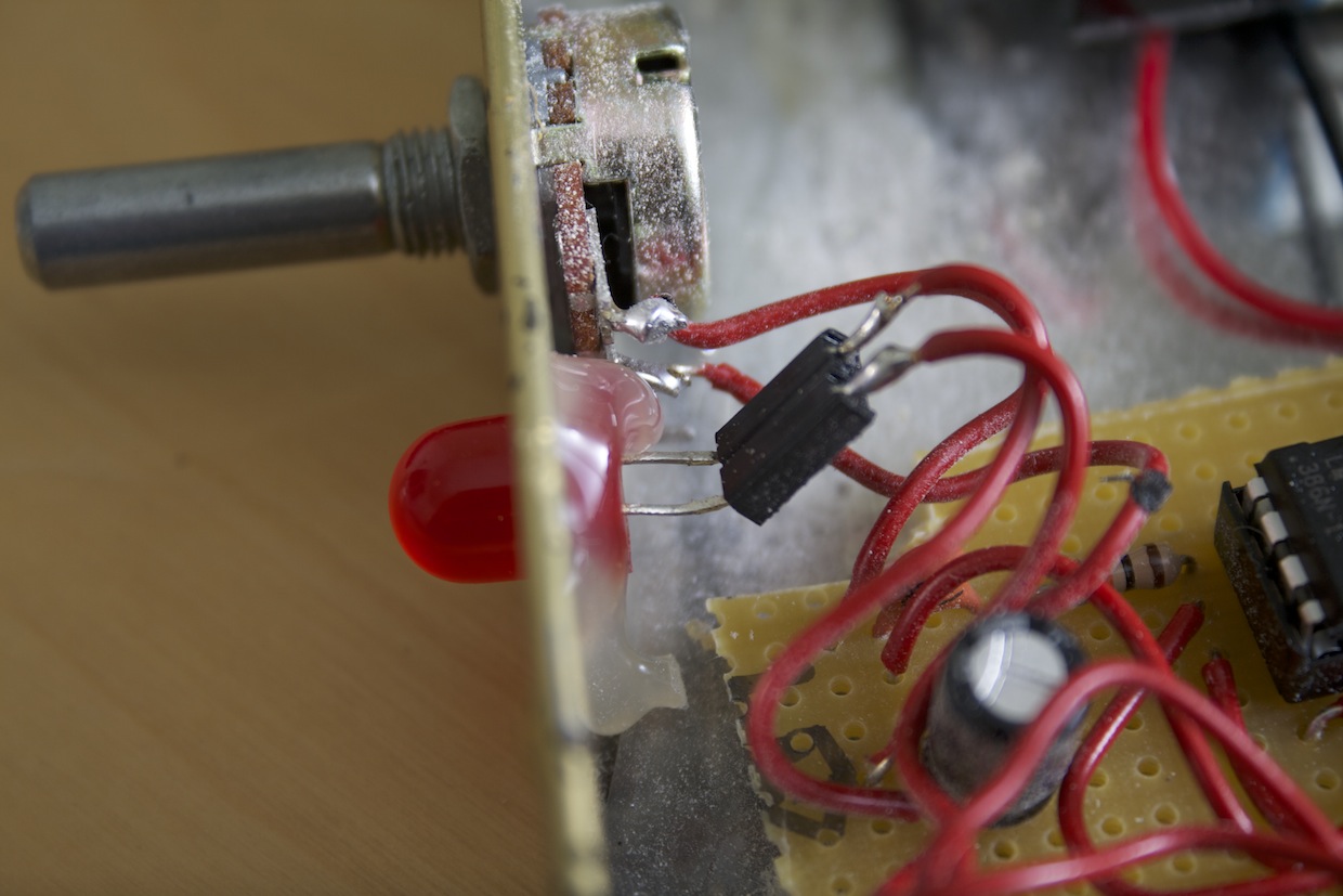
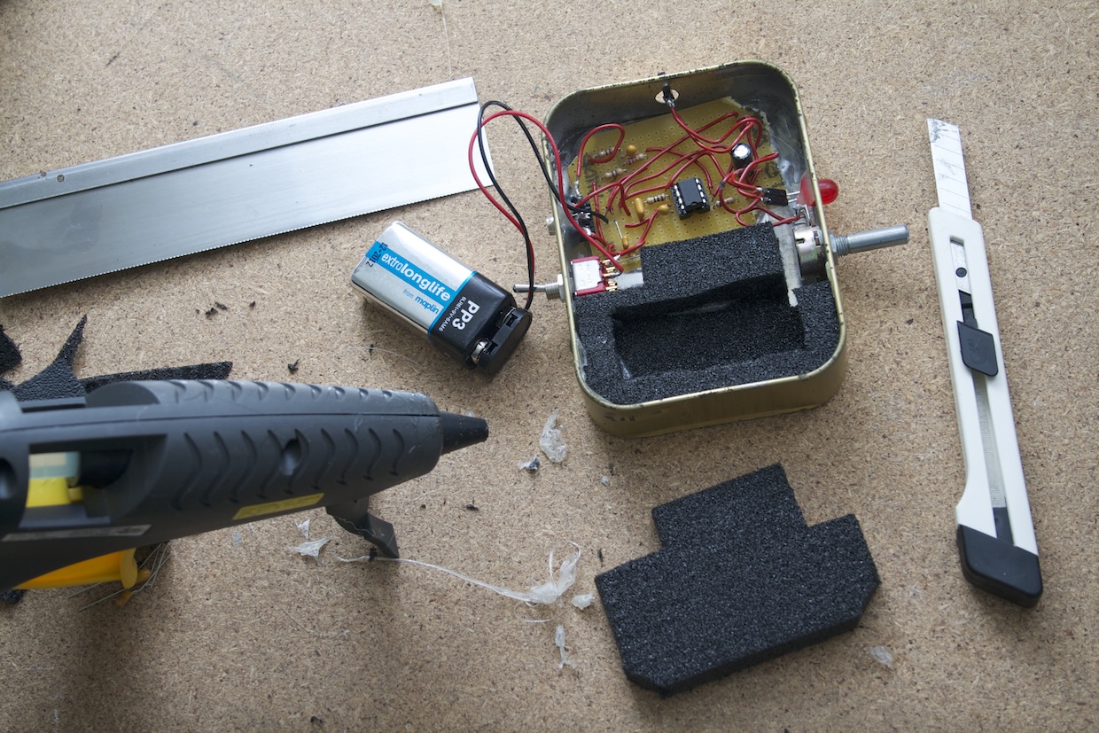
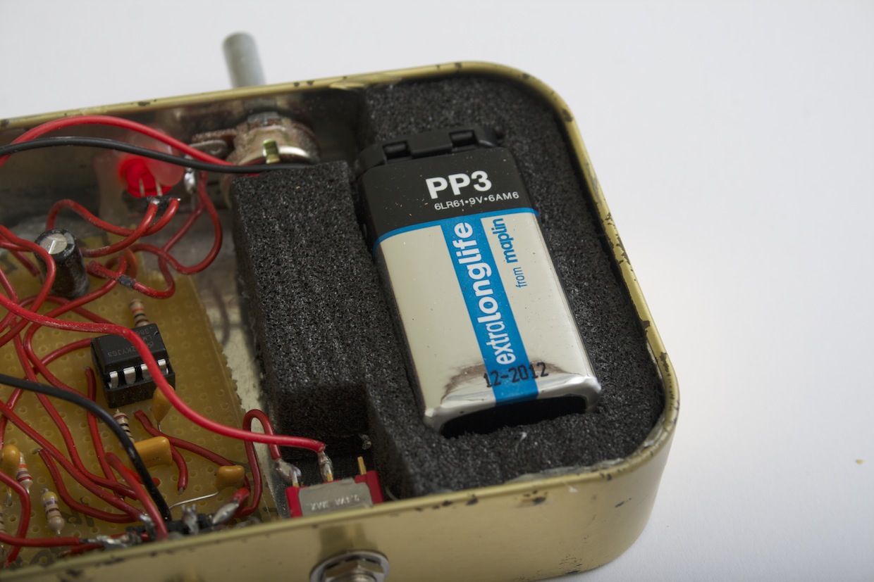
Once the circuit was fully fitted in the box, I made a friction-fit holder for the battery out of plastazote foam.
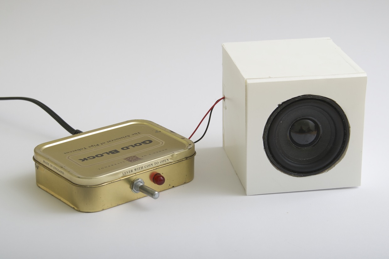
Finally, I made a temporary speaker cabinet out of foamboard, to be replaced when I have a suitable box.
You can see hi-res versions of all these images on Flickr.